Hello,
After some time happily using my TSE, it suddenly stoped working. Rectifier and preamp tubes light up, but power tubes (300b) do not. After quick check I found out that power tubes filament voltage is 0,2V instead 5V.
I guess that sharp voltage regulator is dead, probably due to insufficient cooling. There are no visible marks of burning out on regulator and surrounding parts, adjacent diode seems to be working properly, because preamp tubes are working well.
I will be ordering replacemet, but want to be sure - is there any way to check it without unsoldering?
Insufficiente cooling....
Same problem, after 15 min of use of 300B TSE with a preamp, volume go down and B+ grows up to 440V
Identified as a insufficient cooling regulation, put a bigger aluminium cooler but seem still insufficient.
Questions :
1) how big are yours?
2) did you use thermal paste?
Thanks
Same problem, after 15 min of use of 300B TSE with a preamp, volume go down and B+ grows up to 440V
Identified as a insufficient cooling regulation, put a bigger aluminium cooler but seem still insufficient.
Questions :
1) how big are yours?
2) did you use thermal paste?
Thanks
Hello,
After some time happily using my TSE, it suddenly stoped working. Rectifier and preamp tubes light up, but power tubes (300b) do not. After quick check I found out that power tubes filament voltage is 0,2V instead 5V.
I guess that sharp voltage regulator is dead, probably due to insufficient cooling.
As a newby, just add a few thing I need expert to recall :
1) C4 : I'm now on a 370V for B+ and would like yo go up to 400V, actually using a 22uF electrolytic capacitor; question : to make B+ go up should put a bigger or smaller capacitor? would a film cap would better than elctrolytic?
2) C5 : understand that bigger is better and electrolytic is OK (now have a 300uF);
3) I'm going to use a preamp, so I understand that wouldn´t be necessary to use a volume pot; question : should still put a 50K resistor (where??) or not because the input resistance comes from the preamp [that's what I think]
Many thanks as usual
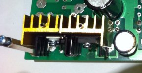
I have attached pic of additional cooler I used for sharp regulator. I used it with mica pad and without thermal paste. It worked until I decided to change power tubes to ones that draw more filament current. I did not experience any fluctuations in B+ or bias current. It was working fine, I switched it off after 6 hours of music listening and next day it did not start.
Diode is working fine, because preamp tubes are working normally and according to schematics they use rectified voltage with 2.2R drop resistor. I suppose they would not conduct if diode would be dead.
My case is Modushop slim 2u, made of aluminium with thick sides. I will mount sharp regulator off board with thermal paste this time and hope that 350 grams of aluminum will be sufficient to keep it cool.
Diode is working fine, because preamp tubes are working normally and according to schematics they use rectified voltage with 2.2R drop resistor. I suppose they would not conduct if diode would be dead.
My case is Modushop slim 2u, made of aluminium with thick sides. I will mount sharp regulator off board with thermal paste this time
and hope that 350 grams of aluminum will be sufficient to keep it cool. Attachments
1) C4 : I'm now on a 370V for B+ and would like yo go up to 400V, actually using a 22uF electrolytic capacitor; question : to make B+ go up should put a bigger or smaller capacitor? would a film cap would better than elctrolytic?
increase cap, but not more than 47 uF
3) I'm going to use a preamp, so I understand that wouldn´t be necessary to use a volume pot; question : should still put a 50K resistor (where??) or not because the input resistance comes from the preamp [that's what I think]
I used 10K volume pot on TSE and 50K on SSE. I have no idea if you need any additional resistors in case you are not using pot (probably not, but that will depend on your source) - I took into account Tubelab advice he made here on 1st November 2010, 01:48 PM:
"The volume pot value for most tube amps (and all of mine) is bounded on the lower end by what the source can drive. I have used a 500 ohm pot on an amp that was fed by a Sony Discman's headphone jack. It is bounded on the upper end by the miller capacitance of the input tube. 100K is about the limit on the SSE and SSP (12AT7) and 50K on the TSE (5842). "
Check the diodes that feed that leg of the power supply. Do you see voltage at the input of the regulator?
Thanks for pointing out possible cause (or onsequence) of problem - I checked all filament supply diodes with multimeter in circuit and it seems that they are faulty - current flows in both directions, so I have to replace all them. Now what might be the cause?
Multimeter reads 550/1100 for both dn 5401 and 100/1600 for dual shottky.
Amp is alive again - diodes were not damaged, out of circuit they passed test. However I replaced 3 amp rated 1N5401 with MUR860. If I am not mistaken, according to datasheets 2=1.2A+2x0,3A =3A total filament current. Using 3 amp rated diodes leaves no safety margin for standard 300b tubes.
Moved voltage regulator off board, this time used thermal paste - tonight will run amp for longer period of time to check temperatures. Yesterday just connected up dummy load and checked voltages and tube bias: filaments 4,96V, B+450V, B-312V, preamp tubes +175V, power tubes bias 68 mA stable for 30 minutes.
Moved voltage regulator off board, this time used thermal paste - tonight will run amp for longer period of time to check temperatures. Yesterday just connected up dummy load and checked voltages and tube bias: filaments 4,96V, B+450V, B-312V, preamp tubes +175V, power tubes bias 68 mA stable for 30 minutes.
Those heat sinks are tiny. Always use either a SilPad thermal pad (Bergquist SilPad 1500ST is about as good as it gets and is available at Mouser) or thermal grease (Wakefield 120 or 126). It's remarkable how big a difference a good thermal interface makes on the thermal performance of power electronic parts!
Tom
Tom
Those two diodes are pushed to their limit in a 300B config. They were only meant to provide the bottom half of the DC filament supply for the input tubes. 300Bs need twice the heater voltage, so they are forced to power those as well. The top half is handled by a nice Schottky rectifier, which has less drop and therefore less dissipation.
Hi - I finished my TSE and it sounds GREAT. But there is a slight buzz, just audible about 10 feet away. Grounding the input does not remove it it. Before I connect up the scope I just wanted to check: I have only grounded the board at GRD-2, is that correct? Thanks!! Henry
I am getting everything together to build the SE version using George's board. Will I run into any problems mounting the big capacitors under the board much like the SSE build where the board can be mounted closer to the top to a case? I see no reason why not unless they cover a solder joint that another part will need to use. Has anyone else done it this way. This is my second Tubelab build. I just finished building the SSE point to point but I decided on the SE to use a board. I also bought George a hamburger lunch after building the SSE for his time and effort keeping his website up. I like building point to point but the board build for a 300B amp will be challenge enough.
I am having a problem finding the 4 pin socket that will work on the board without flanges. Does anyone have a source for decent ones like the one George is using in his build guide. I bought some big ceramic ones that will have to be mounted to the case and wires run to the board which is not a problem but they have big ceramic flanges as well to deal with.
Tubelab SE First build
A year ago I built the SSE and it is still going strong. This year I decided to build the SE for the 300B tubes.
I've got everything wired up and connected to a Variac. I ran through the checkout and then put in the 300Bs (Electro Harmonix) and then I slowly crank up the Variac and everything is looking great and I get the B+ up to 390V with the bias at 0V and then set the bias to about 60mA and the 5842 plate voltages to 175V. The B+ dropped once the tubes loaded the supply, so I slowly cranked the voltage up continually keeping the bias around 60mA and plate voltage at 175V. Finally I get to about 340V for B+, bias at 60mA and plate at 175V with the Variac at about 94%. It plays for maybe 1min and then B+ goes up and the bias on each of the 300Bs drops to 0 from about 65mA. If I drop the Variac back down to about 50% the bias starts climbing and I can crank the B+ back up to 330V and it will play there for hours.
I haven't finalized all of my heatsinks so if it is a thermal issue perhaps this will resolve the issue. Based on an earlier post I'll monitor the 300B heater voltages to see if they are dropping when this happens.
If that is not the issue, I'm posting this to see if someone has other trouble shooting ideas.
I'm running pretty much standard parts on the circuitboard except I've got a James Choke (5H 200mA 62 Ohm) in place of R4 and have a 10uF in for C4 which was giving me about 420V B+ unloaded. My transformer is a Hammond 376XP and I'm connected to the 120V inputs. My line voltage measures about 125V.
I did blow up C6 during my first checkout and found that I had missed the centertap connection to ground for the HV inputs from the transformer. All voltages were good once I replaced C6 and made the proper centertap connection. Per my DVM the 300B Heaters were at 4.97V and the 5842 heaters were at 6.38V.
Thanks,
If you are willing to pay a little more and wait for delivery from China I found some nice ceramic ones with gold pins on eBay. 1pc 4pin Gold Ceramic Vacuum Tube Valve Socket for 300B 2A3 801 274A Audio Amps | eBay.I am having a problem finding the 4 pin socket that will work on the board without flanges. Does anyone have a source for decent ones like the one George is using in his build guide. I bought some big ceramic ones that will have to be mounted to the case and wires run to the board which is not a problem but they have big ceramic flanges as well to deal with.
I made a lower offer and they accepted.
- Status
- This old topic is closed. If you want to reopen this topic, contact a moderator using the "Report Post" button.
- Home
- More Vendors...
- Tubelab
- Tubelab SE