No, terminal 6 is not connected to the case, it goes inside a resine block which makes invisible what happen inside, but is the "choke".
I'll try t ask the vendor
Asked the vendor, the GND comnnection could be used or not, it is for RF shielding....
Thanks
Asked the vendor, the GND comnnection could be used or not, it is for RF shielding....
Thanks
That makes sense, you want to tie that to ground.
Hi,
Well, after some running time, i connected the "Still naked TSE" to my good speakers - CANTON 490 GLE.
I can Just say that the sound is clear and dynamic.
I'm so pleased with the Amp
Still i have a long way till finishing it.
After grounding every piece of metal, i now have a little bzz from the PT. It's very quite but still i wish to remove it. What can cause that?
Boywonder:
I need your help with the power connector.
1) Where did you bought your connector and the wires?
2) How many pins does it have? (I tought about 8 pin)
Thanks...
My tubelab SE is still my favorite amp....
Ran: If the power transformers buzzes slightly when you put your ear right next to it, that's normal.
For my umbilical cable, the connectors are AMP circular plastic connectors (CPC series) 9 pin. I started out using 8 of the pins but had a hum problem since I was using a common conductor for both signal and chassis ground and ended up using all 9 pins. The panel mount connector on the amp uses male pins and the cable side has sockets for safety. Keep in mind that with 9 conductors if the cable is disconnected from the amp with the transformer plugged in you have 400-500 VAC on two of the exposed sockets.
The cable was a work project left-over. It's hard to find in small lengths, especially 600V rated wire for the B+ conductors.
If I was doing it again, I would use individual wires (600V wire for the B+ and 300V wire for the others) covered in braid. I would also use at least 11 pins and have the extra two pins connected together on the amp side forming a mains switch back at the transformer so that when the umbilical is unplugged you don't have high voltage on the exposed sockets.
I can draw a diagram for this if you need. If you decide to go this way, I can also crimp the contacts on your wires as I have lots of crimpers for this sort of thing.
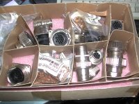
Amphenol also makes mil-spec metal shelled circular connectors but they are $$.
Here are some links to the parts (roughly):
Invalid Request
Invalid Request
Invalid Request
If you go this way, I can assist with the exact selection of housings, terminals, etc.........or you can just build a single chassis ;-)
Here is a picture of the metal-shelled Amphenol mil spec connectors:
After grounding every piece of metal, i now have a little bzz from the PT. It's very quite but still i wish to remove it. What can cause that?
Boywonder:
I need your help with the power connector.
1) Where did you bought your connector and the wires?
2) How many pins does it have? (I tought about 8 pin)
Thanks...
Ran: If the power transformers buzzes slightly when you put your ear right next to it, that's normal.
For my umbilical cable, the connectors are AMP circular plastic connectors (CPC series) 9 pin. I started out using 8 of the pins but had a hum problem since I was using a common conductor for both signal and chassis ground and ended up using all 9 pins. The panel mount connector on the amp uses male pins and the cable side has sockets for safety. Keep in mind that with 9 conductors if the cable is disconnected from the amp with the transformer plugged in you have 400-500 VAC on two of the exposed sockets.
The cable was a work project left-over. It's hard to find in small lengths, especially 600V rated wire for the B+ conductors.
If I was doing it again, I would use individual wires (600V wire for the B+ and 300V wire for the others) covered in braid. I would also use at least 11 pins and have the extra two pins connected together on the amp side forming a mains switch back at the transformer so that when the umbilical is unplugged you don't have high voltage on the exposed sockets.
I can draw a diagram for this if you need. If you decide to go this way, I can also crimp the contacts on your wires as I have lots of crimpers for this sort of thing.
Amphenol also makes mil-spec metal shelled circular connectors but they are $$.
Here are some links to the parts (roughly):
Invalid Request
Invalid Request
Invalid Request
If you go this way, I can assist with the exact selection of housings, terminals, etc.........or you can just build a single chassis ;-)
Here is a picture of the metal-shelled Amphenol mil spec connectors:
Attachments
Last edited:
Finally I breadboarded my TSE and made initial checkout (I am still waiting for my 300b's, so it was not possible to do final checkout.
With rectifier and premp tubes in, I measure such voltages:
B+ 474V
B- 393V
Both power tube filaments 4.93V
Power tube grid to ground - 368V each (most negative)
Driver tubes plate to ground 176V each (after setting)
Seems to be ok, just worried a bit with B+. For initial checkout C4, I connected in series 4.7uF and 6.8 uF 450V capacitors - if I calculated well, total C4 capacitance should be 2.8 uF and I am getting crazy B+ value.
I hope that it will go down to 390V with power tubes installed.
I breadboarded my TSE and made initial checkout (I am still waiting for my 300b's, so it was not possible to do final checkout.With rectifier and premp tubes in, I measure such voltages:
B+ 474V
B- 393V
Both power tube filaments 4.93V
Power tube grid to ground - 368V each (most negative)
Driver tubes plate to ground 176V each (after setting)
Seems to be ok, just worried a bit with B+. For initial checkout C4, I connected in series 4.7uF and 6.8 uF 450V capacitors - if I calculated well, total C4 capacitance should be 2.8 uF and I am getting crazy B+ value.
I hope that it will go down to 390V with power tubes installed.
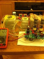
Just received my 300b's and did final checkout.
With rectifier and premp tubes in, I measured such voltages:
B+ 453V
B- 316V
Both power tube filaments 4.93V
Power tube grid to ground - 142V and -136 (most negative)
Driver tubes plate to ground 175V each (after setting)
With dummy 8 ohm load I set both power tubes to 51mA, driver tubes plate to ground was 175v stable, B+ fluctuated between 420 and 426V.
I connected speakers and am currently playing music. No hum so far, but bias of both power tubes constantly fluctuates between 50-54 ma. Is it normal?
I am really concerned with B+ at 420-425 volts at the moment it is probably too much for psvane hifi series 300b's in long term. I measured capacitance of c4 - it is 2,7 uF.
I will try 1uF, but still do not understand how Ran with exactly same iron and mains voltage 230v is getting 380V B+ with 7,6 uF cap at C4.
By the way, it sounds nice. Not sure yet if sound is better than my sse but it is unfair comparison - sse is fully burned in, and tse was playing just 1 hour.
Yes, bias moving around with music playing is normal.
Ran may be running higher bias current, that will reduce the B+ for a given PS config. I'm running my TSE at about 360V/60ma IIRC. Trying cranking up your bias to 60ma and let us know what your B+ voltage is.
Yes, bias moving around with music playing is normal.
Ran may be running higher bias current, that will reduce the B+ for a given PS config. I'm running my TSE at about 360V/60ma IIRC. Trying cranking up your bias to 60ma and let us know what your B+ voltage is.
My TSE is with the follow configuartion:
For PT: JS-9612
Inductor: JS-10-200S 10mH 97ohm
Main: 230V
PT: 350V
C4: 7.6uF
Driver tubes: 175V
300B Bais: 65mA
B+: 382V
Last edited:
I was afraid increase current - went to 55mA, but B+ did not seem to go any lower, so I made listening test with 50mA on each tube.
Besides that, numbers did not match with ones that Ran posted earlier and Psud II simulation with load of 125 mA simulates B+ 350V - I am off more than 70 volts, so thought that something was wrong. Probably I must measure my mains voltage - last time it was spot on 230V, but it was measured year ago.
My configuration is such:
Power transformer: JS-9612
Choke: JS-10-200S 10mH 97ohm
Mains: 230V
High voltage tap - 350V-0-350V
C4: 2,7uF
Driver tubes: 176V
300B Bias: 52mA
B+: 425V
I ordered set of 2.2 and 4.5 uF 450V electrolytic caps - will connect them in series for total capacitances of 2.35uF, 1.5 uF, 1,1 uF and 0,7 uF. I will probably do another test with C4=2,35 uF in order to see the efffect on B+ and will try to bias power tubes to 65 mA each. I was planning to run them at 380-390V 70 mA, but now I am not sure anymore.
Hopefully tubes will survive - George posted somewhere on his website that modern production 300b's go into runaway condition if used with B+ above 400V.
Attachments
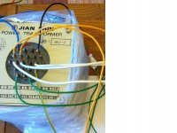
Ran, thank you for a tip, it makes sense. I am posting picture of my PT wiring - it seems to be right 350-0-350. But I must obviously check it - they might have soldered secondaries to wrong pins in factory
It should not be the case as PT seemed to be factory tested, but you never know - I will measure and post values of all secondaries along with mains voltage.
It will be lol if they mixed stuff up
It should not be the case as PT seemed to be factory tested, but you never know - I will measure and post values of all secondaries along with mains voltage.
It will be lol if they mixed stuff up
Attachments
I ordered set of 2.2 and 4.5 uF 450V electrolytic caps -
For those values I would use film caps, they are affordable and reasonably sized. A basic film cap (like a Solen) will outperform a boutique electrolytic and they are available in 600V rating.
You can get your B+ lower by lowering the first cap value. Pick up a few values less than 1uf like .22uf, 33uf etc and try them. Vanilla no-name film caps work great for these tests.
The lowest that you can get will be about 90% of your transformer secondary (pseudo L-C supply with a tiny first cap)
Do you have different primary taps on the 9612 like 220V and 230V?
It does seem odd that your B+ is so different than Rans with exactly the same PS components.....
I am confused - Pt secondries are ok, these are my voltages at no load:
Mains 230V actual is 232V.
The only primary for pt is 230 V (2x 0-115V in series)
Both 6.3v 4a secondaries are 6.33V
5v 6a secondary is 5.07V
700V secondary is 712V
800V secondary is 814V
I connected to board 350-0-350 and do not understand why I get such high B+. It seems that now I must crank up bias to 70mA to see how much B+ drops with current capacitor value as boywonder suggested. I will post my findings after that.
Regarding type of caps - I use dirt cheap electrolytics in series for start up, but I have purchased audyn MKP Q6 8.2 F 600v for C4 based on values that Ran was posting, however in my case it seems to be useless. I will use film cap after I will tune B+ to desired value.
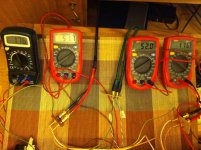
 I am stupid - I was biasing power tubes not 70 mA, but 7 mA. I was rather surprised that tse was playing music more silent than sse and then checked multimeter scale.
Now my B+ is 324 V, bias 70 mA, so I guess it is safe to put 8.2 uF C4 film cap for 400B+.
Thank you boywonder and Ran for help. Will run it breadboarded for some time for break-in, enjoying HD Acis and Galatea performed by Dunedin Consort
It probably was not the best idea to use cheap electrolytics in series for C4 - after couple of hours playing I noticed strange smell and bias of power tubes went down to 44mA from 71 mA, B+ also drifted down from 325 to 270 Volts.
One of caps that were in series started leaking and oak board below them was soaked with electrolyte. So I guess I have to finally put film cap there before making any furhter listening tests.
One of caps that were in series started leaking and oak board below them was soaked with electrolyte. So I guess I have to finally put film cap there before making any furhter listening tests.
It probably was not the best idea to use cheap electrolytics in series for C4 - after couple of hours playing I noticed strange smell and bias of power tubes went down to 44mA from 71 mA, B+ also drifted down from 325 to 270 Volts.
One of caps that were in series started leaking and oak board below them was soaked with electrolyte. So I guess I have to finally put film cap there before making any furhter listening tests.
What was the voltage rating of that cap?
When you run HV caps in series you need equal value resistors across each cap (like 220K or so) or the differing ESR of the caps will result in one taking more voltage drop than the other. The resistors are a simple voltage divider forcing the node between them to be half way between B+ and ground. I suppose you could pick unequal resistor values of your caps have different voltage ratings.
It makes sense - I did not put any resistors across capacitors, both of them were 450V rated, but different capacities - that probably had negative effect too. I will take it into acount for future projects. I have 8.2 uF film cap with 600V rating that was dedicated for that position, I will simply put it instead of those leaking electrolytics - anyway I was planning to use them only for initial tests to dial-in B+.
I see that what I get with 2.7 uF cap is close to simulated result of PSUD I, so it is safe to asume that with 8.2 uF I will have close to 400V B+.
I see that what I get with 2.7 uF cap is close to simulated result of PSUD I, so it is safe to asume that with 8.2 uF I will have close to 400V B+.
Hi there,
After 10 month i all most finished my case for the Amp (changed a job, got engaged, moved a house).
I got a lot of help from Boywonder (He also made me a cable like his Thanks)
I have placed all the components into the cases and started the tests from the beginning.
In the stage when i plug the 5482 in i have stopped, because the voltage on the plate 470V, like the B+ (it's a mirror to the B+ when the Amp is up, but when i turn it Off it gets to 0V much faster then the B+).
How can it be?
(The previous tests were OK, B+ 470V, B- -290V, Bias level -165V )
After 10 month i all most finished my case for the Amp (changed a job, got engaged, moved a house).
I got a lot of help from Boywonder (He also made me a cable like his
Thanks)I have placed all the components into the cases and started the tests from the beginning.
In the stage when i plug the 5482 in i have stopped, because the voltage on the plate 470V, like the B+ (it's a mirror to the B+ when the Amp is up, but when i turn it Off it gets to 0V much faster then the B+).
How can it be?
(The previous tests were OK, B+ 470V, B- -290V, Bias level -165V )
Last edited:
- Status
- This old topic is closed. If you want to reopen this topic, contact a moderator using the "Report Post" button.
- Home
- More Vendors...
- Tubelab
- Tubelab SE