Is terminal 6 connected to the case/mounting screws?
Apparently not, but I'll check better.
Thanks
Just for start, I have placed a 2.2uF that give me the 310V B+.
I'll now change it to 8.2uF to get 390V B+.
R18 and R29 have a voltage of around 670mV (I wrote R10 &R29, a mistake by my)
Your DC conditions seem fine......390 B+ and 67ma per tube. Have you adjusted the 5842 anodes to around 175V?
For your hum issue, I would focus on the pot/attenuator grounding. Do you have some cheap speakers to use for troubleshooting? .....or better yet, a couple of load resistors and a scope?
How is the attenuator grounded? Are you using a star grounding scheme with only one point on the chassis where all of your grounds connect?
Faulty pot grounding can blow speakers in a hurry.......don't ask me how I know this.....
Your DC conditions seem fine......390 B+ and 67ma per tube. Have you adjusted the 5842 anodes to around 175V?
Working with 480V B+, 5842 still with 150V (will change the 512ohm resistor to 1K ASAP).
Current on the 10ohm resistors is 68mA.
Have a cheap speakers, and mybe a scope tomorow.For your hum issue, I would focus on the pot/attenuator grounding. Do you have some cheap speakers to use for troubleshooting? .....or better yet, a couple of load resistors and a scope?
How is the attenuator grounded? Are you using a star grounding scheme with only one point on the chassis where all of your grounds connect?
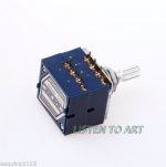
The pot is ALPS 50K LOG.
As you can see in the picture there 3 pins for each channel. The groung wire is attached to the metalic volume pin.
ground wiring:
1) Main ground to the pot.
2) Main ground to right channel speaker.
3) A wire from the right channel to the left channel.
When the CD is playing with sound to minimum there is no hum.
Till a reasonable volume there is no hum.
From this point any increasement will cause a hum. WHen the hum apear the current on the 10ohm resistor increases up to 80mA and even more, is that OK?
Attachments
1) I run the 300B with 380V B+.
2) about the grounding, in the grounding diagram of the SSE i see that the input is grounded, that mean that T1-1 is grounded -> 350V CT is grounded. am i worng?
The last time i grounded nothing worked.
3) Can the hum be caused from saturation? (because it happens after turning the volume up)
4) All the transformers, chock, board are conected to a wooden board. do i have to connect all the bolts to the ground?
1)
3) Can the hum be caused from saturation? (because it happens after turning the volume up)
4) All the transformers, chock, board are conected to a wooden board. do i have to connect all the bolts to the ground?
Re:#3
Like previously mentioned in this thread, the pot needs to be grounded. That is probably why you have volume related hum.
Re:#4
Each transformer and choke should have one bolt grounded. This may reduce hum, but is really for safety.
Re:#3
Like previously mentioned in this thread, the pot needs to be grounded. That is probably why you have volume related hum.
Thanks, but i did connect the pot directly to main ground.
Thanks, but i did connect the pot directly to main ground.
Do you have a preamp or other means to change the volume of a source? If so, as a test, replace/bypass the pot with a 50K resistor and see if the hum goes away.
about the grounding, in the grounding diagram of the SSE i see that the input is grounded, that mean that T1-1 is grounded -> 350V CT is grounded. am i worng?
(The last time i grounded it by mistake nothing worked.)
Correct, the power transformer CT is grounded. With the B+ voltages that you have, your CT is also grounded. To convince yourself of this, check for continuity between the CT and chassis ground. Tie all of the grounds to one stud on the chassis (star ground).
If your signal grounds are not connected to chassis (at one point) this could also be contributing to your hum issue.
Is terminal 6 connected to the case/mounting screws?
No, terminal 6 is not connected to the case, it goes inside a resine block which makes invisible what happen inside, but is the "choke".
I'll try t ask the vendor
Another qustion I have is about "hybrid rectifier" : I understand that using it would help to smoothen the B+ raising, is that correct?
In schemes I've always seen the use of two diodes before the tube rectifier, would it be bad to put a full diode rectifier before the 5AR4?
In schemes I've always seen the use of two diodes before the tube rectifier, would it be bad to put a full diode rectifier before the 5AR4?
I connected the ground to the board and the hum disappeared.
Yahhhh
Running with B+ 380V, 300B current is 70uF, 5842 150V.
The sound is good but a little bit to much bass.
I will connect the 220uF CLARITYCAP now and see how the sound change. (Low ESR)
After I'll increase the 5842 voltage from 150V to 175V.
I know the 300B has good bass but can I get little more mid? If yes, how?
Thanks you all, boywonder especially
Now the long episode of case building starts
I am happy that it worked out for you.
By the way, I just received James iron - silver color, so it looks like my tse will be similar to yours.
As I understand you are getting B+ 380V with 8,4uF capacitor in C4. Is that true?
Right now I use a composite capacitors that give me 7.6uF.
With primary of 230V, the tap of 350V and that capacitors value I get 380V.
I have changed the 5842 stoper resistor from 512 to 1K so i could rise the voltage from 150V to 175V.
After i set the voltage to 175V i put the 300B and set the bias current to 69mA.
Then i checked again the 5842 plate voltage and now it's 181V. is it normal or do i have to do iteration again?
After i set the voltage to 175V i put the 300B and set the bias current to 69mA.
Then i checked again the 5842 plate voltage and now it's 181V. is it normal or do i have to do iteration again?
I have changed the 5842 stoper resistor from 512 to 1K so i could rise the voltage from 150V to 175V.
After i set the voltage to 175V i put the 300B and set the bias current to 69mA.
Then i checked again the 5842 plate voltage and now it's 181V. is it normal or do i have to do iteration again?
You mean the 5842 cathode R.....?
Yes, iterate. When you increase the bias current, the B+ drops, affecting the 5842 and 300B anode voltages.
For reference, if the amp had regulated supplies, the B+ wouldn't change with current draw. Like lots of things, some folks like regulation and some don't.
In my case, 5842 plate to ground voltage slowly rises for about 15 - 20 minutes after power up and then stabilizes. That's when I adjust it to 175V.I have changed the 5842 stoper resistor from 512 to 1K so i could rise the voltage from 150V to 175V.
After i set the voltage to 175V i put the 300B and set the bias current to 69mA.
Then i checked again the 5842 plate voltage and now it's 181V. is it normal or do i have to do iteration again?
- Status
- This old topic is closed. If you want to reopen this topic, contact a moderator using the "Report Post" button.
- Home
- More Vendors...
- Tubelab
- Tubelab SE