Hi,
If the output of you DAC is way below the 2V RMS standard I'd advise using a preamp with some amplification.
Provided that preamp has low enough Zo and you keep connections from the DAC to it short it would solve all the problems in one go.
Cheers,")
I guess that for us who are fiddling around with passive conversion with dacs, where the output is quite low, some amplification with the tube could be beneficial.
If the output of you DAC is way below the 2V RMS standard I'd advise using a preamp with some amplification.
Provided that preamp has low enough Zo and you keep connections from the DAC to it short it would solve all the problems in one go.
Cheers,
Hi
All my first post but had several emails with NUUK..
Lee
I have been following this thread having built several GC's for friends,I am going to try the hybrid version soon..
I can tell you that DC heating is almost mandatory,if you can not get a supply running try powering the heaters from a battery source.Four AA cells should be ok,and will last long enough to tell wether AC is the problem.
Regards
Peter
Peter,
I will definitely try the batteries, but the noise exists even when the tube is not powered so I tend to think I have a grounding issue somewhere. But since this is the first time I am using multiple transformers and because the noise is equal in both channels I also agree it could be the AC on the filament. I will take another look tonight a report back what I find.
Regards...Lee
Hi,
I haven't followed the thread from top to bottom but if the tube isn't powered then the amp won't work either... unless you resistively bypass the tube stage.
That would give you a humming noise...wasn't that tube supposed to be fed by DC?
Cheers,
I will definitely try the batteries, but the noise exists even when the tube is not powered
I haven't followed the thread from top to bottom but if the tube isn't powered then the amp won't work either... unless you resistively bypass the tube stage.
I also agree it could be the AC on the filament
That would give you a humming noise...wasn't that tube supposed to be fed by DC?
Cheers,
That would give you a humming noise...wasn't that tube supposed to be fed by DC?
Yeah Joe's schematic showed DC, but my original PS wasn't working so I scrapped it for a 6.3-0-6.3 one I had hanging around. If I rectify that supply I'm going to end up with around 9 volts on the filaments which will probably burn out the tube.
Any ideas on how I can rectify and still get 6.3v.
Thanks...Lee
Hi,
Yes, you could use a simple 7806 for a start, although a 3V drop won't make it very happy...a LM317 would work better here...athough just about working too.
There are some low drop 6V regs around but I can't give you the exact reference for those...semi conductors aren't really my field, maybe someone is kind enough to point you to some references.
You could calculate for some series resistance, either infront or after the diode bridge to burn of the excess voltage as well, it's just a temporary arrangement anyway.
Also, if you look further up, at the early stages of this thread, someone posted a circuit that bypassed the tube altogether using a 330R resistor if I recall it correctly.
Either way, hum is easily identifiable through speakers as hum, noise in general is a different ballpark really...
I'm sure that when you dig a little in the "Tubes" section of this forum you may find plenty of inspiration.
Hope this helps,
Any ideas on how I can rectify and still get 6.3v.
Yes, you could use a simple 7806 for a start, although a 3V drop won't make it very happy...a LM317 would work better here...athough just about working too.
There are some low drop 6V regs around but I can't give you the exact reference for those...semi conductors aren't really my field, maybe someone is kind enough to point you to some references.
You could calculate for some series resistance, either infront or after the diode bridge to burn of the excess voltage as well, it's just a temporary arrangement anyway.
Also, if you look further up, at the early stages of this thread, someone posted a circuit that bypassed the tube altogether using a 330R resistor if I recall it correctly.
Either way, hum is easily identifiable through speakers as hum, noise in general is a different ballpark really...
I'm sure that when you dig a little in the "Tubes" section of this forum you may find plenty of inspiration.
Hope this helps,
Hi
Lee
Does the hum stop if you remove the valve.?Maybe your supply has excess ripple
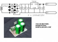
This circuit can be used for the DC supply,this was a mod offered for the WAD amps that suffered hum,althouth the Tx was a nominal 6.3v AC.I rather use something regulated like LM317T than use resistance to drop excess voltage.
Regards
Peter
Lee
Does the hum stop if you remove the valve.?Maybe your supply has excess ripple
This circuit can be used for the DC supply,this was a mod offered for the WAD amps that suffered hum,althouth the Tx was a nominal 6.3v AC.I rather use something regulated like LM317T than use resistance to drop excess voltage.
Regards
Peter
Attachments
Some Progress
It seems that I had a grounding issue. I still have hum but at leasat I can hear music. Now the hum is more what I expect a ground loop or 60mhz to sound like.
I originally had the four grounds from the transformers daisy chained to one connection and connected to the star ground through the cb mic connectors.
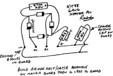
I removed the daisy chain and connected each one directly to the star ground. Noise went away but I still have hum. Now I will look at the AC on the tube (you can see transfo are far rt has no bridge)
The hum is loudest with no volume. When I turn the volume up I perceive a decrease in the amount of hum. I'll let you know what I find next.
Lee
It seems that I had a grounding issue. I still have hum but at leasat I can hear music. Now the hum is more what I expect a ground loop or 60mhz to sound like.
An externally hosted image should be here but it was not working when we last tested it.
I originally had the four grounds from the transformers daisy chained to one connection and connected to the star ground through the cb mic connectors.
I removed the daisy chain and connected each one directly to the star ground. Noise went away but I still have hum. Now I will look at the AC on the tube (you can see transfo are far rt has no bridge)
The hum is loudest with no volume. When I turn the volume up I perceive a decrease in the amount of hum. I'll let you know what I find next.
Lee
Luke said:Hi I have been following this thread for a while and would appreciate someones comments on several questions I have.
Firstly I have tried a few chips now, opa549, opa547 lm3875 and LM3886. I used the same classy Hitano caps from dicksmith
The LM3875 sounded best by long shot I thought. Why then are we and Jeff Rowland using LM3886, is it purely power requirement? I know we are free to choose what we prefer, but wondering if this is the preferred chip for bridging?
Hi Luke.
Sometime back, and I think it might have been this thread, I asked if anyone had had a chance to compare 3875 & 3886. It seems that I've gotten the impression that the 3875 was the better of the two but didn't actually come across anyone who had tried and compared both directly. So I thank you for confirming it.
Re using 3886, you are quite correct, but it isn't so much about power (it's only rated slightly higher than 3875) but it is rated at 75% more current. When bridging where voltage requirements are near halved, that situation translates into added Watts. But not neccessarily better sound.
I am inclined towards the 3875 - I would use the 3886 in this case (bridging only) because I need to build a real 'muscle' amp for a friend. I wish rather he'd change his mucho hungry speakers!
I also noted that increasing the caps from 1000uF to 2200 really killed the sound, I was surprised how different it sounded. Here in Joes design we are using 10000uF. Would the 1000uF on each chips rails not supply enough current to a bridged amp?
Again I am inclined to concur. But you have to support the reservoir depletion to support 100W plus. Again that may not translate to better sound as you suggest, but it becomes a logistic requirement. Again I would prefer to stay with 1000uF for exactly the same reasons stated by you. But it wouldn't work here.
Would Joes circuit with 6 chips per channel work just as well with 4 per channel (understand less power of course) ?
Sure. But you may have to drop the voltage further, say 20V?
Can the bridged version with tube buffer match the quality of a single chip gainclone like kuei yeui yang wang and Peter have kindly given us?
Maybe not. But I have more than sufficent feedback from builders that the single 3875 with tuber buffer (or indeed fet buffer) constructed along the lines of this thread do sound better KYW's (sorry Thorsten).
And my JLTi sounds even better than that. Really!
http://members.ozemail.com.au/~joeras - JLTi Home Page.
Joe R.
PS: You are from New Zealand. Guess what, I am a (non-New) Zealander. Has that got you stumped?
Peter Daniel said:Your observations are in line with mine. Some designers probably don't analyze the sound of a chip as much and go for a higher current version. I will probably try bridged/parallel configuration, but with LM3875 chips. Also, it is said that Jeff Rowland amp doesn't sound that well.
>>Can the bridged version with tube buffer match the quality of a single chip gainclone like kuei yeui yang wang and Peter have kindly given us?<<
I was reading comments in other thread and somebody mentioned trying both single chip and parallel setup and single chip sounded better.
I don't see a problem with using just 4 chips per channel.
There is wisdom in the council of many. Isn't it wonderful when we are all unanimous.

Joe R.
miguel2 said:I guess that for us who are fiddling around with passive conversion with dacs, where the output is quite low, some amplification with the tube could be beneficial.
Miguel
My CD/SACD Player is only 0.7V RMS out, that 10dB below norm. It works well into 90dB efficient speakers. Actually that should be 90dB voltage sensitivity.
Peter Daniel said:Another solution would be using more efficient speakers.
You stole my thunder!

Joe R.
king30 said:Yeah Joe's schematic showed DC, but my original PS wasn't working so I scrapped it for a 6.3-0-6.3 one I had hanging around. If I rectify that supply I'm going to end up with around 9 volts on the filaments which will probably burn out the tube.
Any ideas on how I can rectify and still get 6.3v.
my suggestion
Attachments
Joe Rasmussen said:Sometime back, and I think it might have been this thread, I asked if anyone had had a chance to compare 3875 & 3886. It seems that I've gotten the impression that the 3875 was the better of the two but didn't actually come across anyone who had tried and compared both directly.
Hi, in post 216 (this thread) Vuki says:
"As planed I did a listening session comparing 4 different GC based amps. There were: inverted LM3875 dual mono GC, noninverted LM3886 GC (with 2x2200uF/ch. filter caps), noninverted TDA7294 GC and moamps' hybrid GC.
....
LM3886 was the worst - small soundstage and agressive, dirty highs."
I agree with him.
Regards
Hi Peter,
Ill let you know how I get on, but me thinks joes got this right and its all good Prroblem for me is, Im really busy at work, and every one who's walked through my door want's me to build them a clone, im snowed under. They also all agree my freinds one ie your version, eats mine hands down. Ive ordered the bits and ready to build yours soon. ill post pics cos so far it's looking quite sexy
Joe, thank you for your feedback, you confirmed what I was thinking. I do like a bit of grunt , but dont like to compromise on quality, ther are other options for grunt and I can have both
At present Im
Joe, let me guess you've got Dutch Heritage
Ill let you know how I get on, but me thinks joes got this right and its all good
Prroblem for me is, Im really busy at work, and every one who's walked through my door want's me to build them a clone, im snowed under. They also all agree my freinds one ie your version, eats mine hands down. Ive ordered the bits and ready to build yours soon. ill post pics cos so far it's looking quite sexy Joe, thank you for your feedback, you confirmed what I was thinking. I do like a bit of grunt , but dont like to compromise on quality, ther are other options for grunt and I can have both
At present Im
PS: You are from New Zealand. Guess what, I am a (non-New) Zealander. Has that got you stumped?
Joe, let me guess you've got Dutch Heritage
Tor M said:Hi!
I rewired my tube supply adding two 330 ohm resistor in paralell and a FC1200 cap on + an - supply. The hum is almost gone!!
So thanks!
But now I have another problems (it won`t come easy!) the left channel have half the volume that the right.
I have tested the left channel on both the left and the right power stage and the result is the same, so this has nothing to do with the power amp or the pot.
Both channels of the tubebuffer measures the same regarding DC, no shortcuts...etc, etc. So I don`t know what it is.
I have ordered a new 6922 and I hope that I somehow have managed to damage on of the triodes and that a new tube will solve this.
But the hum is gone!
Tor M
Hi!
One week ago I got my new tube and after that I`ve been busy listening to music!! Sorry for not posting sooner.
The half volume must have been a broken tube (90 days guarantee, so.................)
It sounds great and I`m really hooked too it.
The "big" hum is gone, but unfourtunally I have som source hum when the cd-player is connected and turned on, I probably couldn`t hear that when I had the much louder hum caused by ripple on tube supply. I still have some dc on the right speaker when turning the volume pot, but it`s gone in the left.
I have to try to rearrange the groundings and see if I can get rid of the rest of the hum.
But for now I`m really pleased, and I ordered a bunch of new cds today!!
Have a nice weekend everyone!
Tor Martin
Joe,
You have verified your experiments with LM38xx power opamp and workability of these circuits with Spice simulations in several times now. As long I have searched, I have had no luck to find Spice model for Lm38xx on the web.
Have you found one, created one, or do you use an ideal opamp for these simulations?
If previous, can you please share the model with us? I would like to run some sims before building your tubed version (I’d like to use 6N1Pi tube as buffer and and current source for it). Spice modeling could give a clearer indication for resistor and cap values to use in the input.
Your help is always much appreciated,
Argo
argo said:Joe,
You have verified your experiments with LM38xx power opamp and workability of these circuits with Spice simulations in several times now. As long I have searched, I have had no luck to find Spice model for Lm38xx on the web.
Have you found one, created one, or do you use an ideal opamp for these simulations?
If previous, can you please share the model with us? I would like to run some sims before building your tubed version (I’d like to use 6N1Pi tube as buffer and and current source for it). Spice modeling could give a clearer indication for resistor and cap values to use in the input.
Your help is always much appreciated,
Argo
No I don't have one, it would have been useful. So I did use a generic model. I only used it to sort out how bridged inverted parallel chips would hang together. I used CircuitMaker for that. For filter simulations I use SoundEasy, which is primarily used for louspeaker cross-over modelling - but it has the ability to test active filters. It is very versatile tool. I also use Audiomatica Clio for all sorts of hardware (not simulations) measurements, like spectral distortion graphs like the ones you will see on this page:
http://members.ozemail.com.au/~lisaras/gainclonesound.htm
Does anyone know of a Spice model for LM38xx or similar?
Using 6N1Pi tube as buffer with current source? Go for it!
Joe R.
PS: Has anyone built and compared LM1875 with LM3875?
Luke said:Hi Peter,
Ill let you know how I get on, but me thinks joes got this right and its all good
Joe, thank you for your feedback, you confirmed what I was thinking. I do like a bit of grunt , but dont like to compromise on quality, ther are other options for grunt and I can have both
At present Im
Joe, let me guess you've got Dutch Heritage
Not Dutch? Guess again!
I'd just like to restate the case for using a buffer in front of an inverted circuit. The gains are easy to hear, better dynamics and natural life with improved soundtage (but this requires tweaking the bandwidth). But I admit that this can also be achieved both fets or tubes. Hope you don't mind if prefer tubes, but that's just little ol' me.
Thanks for the kind words.
Looking forward to seeing your snaps.
Joe R.
moamps said:
Hi, in post 216 (this thread) Vuki says:
"As planed I did a listening session comparing 4 different GC based amps. There were: inverted LM3875 dual mono GC, noninverted LM3886 GC (with 2x2200uF/ch. filter caps), noninverted TDA7294 GC and moamps' hybrid GC.
....
LM3886 was the worst - small soundstage and agressive, dirty highs."
I agree with him.
Regards
Thanks moamps for that.
Now has anyone come across anyone stating results LM3875 versus LM1875 (the one used in the Gaincard). Does the latter have an advantage again over the 3875, as the 3875 does over 3886. I am now reconsidering using 3886 at all and simply go with 3875 x 6 in the bridged parallel amp I may be building. The higher current capability might have to be foregone.
Regards
Joe R.
ARRGHH!
Sorry for bothering everybody, but now I really need some help.
My new 6922 suddenly died, this time in the right channel. It`s playing half volume like the last one did in the left channel.
My current setup is like Joe`s schematics but with the pi filter with 165 ohm resistor and Fc 1200uF capasitor.
The filament votage is 6.3 V using 15VA 2 X 9 V, one bridge, lm 317 using a 2k multiturn pot and a 330 ohm resistor to set voltage at exactly 6.3 V
The cathodes are -42,2V and anodes are +42,8V.
I hope I can get new tubes on the 90 days guarante.
The electricity in my house are kind of rotten, and I can hear power transients in the speakers when somebody is turining a light swich.
My cdplayer has 10 mV of dc on the outputs.
Anybody have any Idea why the tubes are getting damaged?
(If I could put those two tubes together I now would have one working )
Tor Martin
Sorry for bothering everybody, but now I really need some help.
My new 6922 suddenly died, this time in the right channel. It`s playing half volume like the last one did in the left channel.
My current setup is like Joe`s schematics but with the pi filter with 165 ohm resistor and Fc 1200uF capasitor.
The filament votage is 6.3 V using 15VA 2 X 9 V, one bridge, lm 317 using a 2k multiturn pot and a 330 ohm resistor to set voltage at exactly 6.3 V
The cathodes are -42,2V and anodes are +42,8V.
I hope I can get new tubes on the 90 days guarante.
The electricity in my house are kind of rotten, and I can hear power transients in the speakers when somebody is turining a light swich.
My cdplayer has 10 mV of dc on the outputs.
Anybody have any Idea why the tubes are getting damaged?
(If I could put those two tubes together I now would have one working
) Tor Martin- Status
- This old topic is closed. If you want to reopen this topic, contact a moderator using the "Report Post" button.
- Home
- Amplifiers
- Chip Amps
- Tube with Power IC Output Stage - JLTi