Hi,
Yep, I thought it was a bit odd in that there was no series R.
Just an idea: wouldn't it then be better to move the 1uF filmcap to the last cap ( the 100uF) ?
Have nice weekend,")
P.S. I am assuming you mean the PSU here:
MAIN POWER SUPPLY
Did anyone spot my earlier mistake re Pi filter... ???
Yep, I thought it was a bit odd in that there was no series R.
My suggested fix, if my hunch is right, is to add an RC filter, something like 220 Ohm and 100uF (min) after the 1000uF. Give that a go.
Just an idea: wouldn't it then be better to move the 1uF filmcap to the last cap ( the 100uF) ?
Have nice weekend,
P.S. I am assuming you mean the PSU here:
MAIN POWER SUPPLY
fdegrove said:Hi,
Yep, I thought it was a bit odd in that there was no series R.
You get the eagle eyes award!
Actually the Pi filter would require a series L, which looks like moamps did.
Just an idea: wouldn't it then be better to move the 1uF filmcap to the last cap ( the 100uF) ?
Have nice weekend,
P.S. I am assuming you mean the PSU here:
MAIN POWER SUPPLY
Exactly!
Here is the revision of that part of the schematic:
An externally hosted image should be here but it was not working when we last tested it.
I hope this will fix Tor's hum.
JR
Thanks Joe!
I spotted your post and I`ve been looking in my drawer to see if I could find any parts.
I can`t find any 100 uF caps, but I found some Starget 47uF 35 V and 330 ohm resistors.
If I parallel two of the Stargets can they then stand more than the rated 35 V og would I still need 50 V caps?confused:
Will 330 ohm resistors bee to much?
Thanks. I really appriciate you taking the time to help me!!!!
Tor Martin
Hi Tor,
If Joe doesn't mind my answering for him:
The 35V caps are risky to use there since the rail is +/- 35V already.
You could use them in series with voltage balancing resistors but you'll end up with half the capacitance and twice the insulation voltage: 23.5uF/70V.
Any insulation voltage higher than 45V should be O.K., maybe you can find some 100uF/100V or even higher?
The 330R resistor should work, the idea is to replace the Ri of the buffer with the resistor.
Hope this helps,
I can`t find any 100 uF caps, but I found some Starget 47uF 35 V and 330 ohm resistors.
If Joe doesn't mind my answering for him:
The 35V caps are risky to use there since the rail is +/- 35V already.
You could use them in series with voltage balancing resistors but you'll end up with half the capacitance and twice the insulation voltage: 23.5uF/70V.
Any insulation voltage higher than 45V should be O.K., maybe you can find some 100uF/100V or even higher?
The 330R resistor should work, the idea is to replace the Ri of the buffer with the resistor.
Hope this helps,
Yep, thought so.
I don`t think I have any 100uF capasitors. I found some big Mundorf 68uF elektro glatt capasitors. But those are only ac rated (35 V), not dc rated.
I`ve got lots of Panasonic FC1200uF. A little to big!!
Maybe I can find something in a broken cd player I have laying around.
Have to order some parts this week, I`ll order some then.
Thanks
Tor Martin
Hi,
If you're sure they're AC rated then that should do it.
I don't think the absolute uF value of the cap would be all that crucial, so give both a try if the Pana is within voltage spec...
Ah...too late for action...Dave has beaten me to it.
Cheers,
I found some big Mundorf 68uF elektro glatt capasitors. But those are only ac rated (35 V), not dc rated.
If you're sure they're AC rated then that should do it.
I don't think the absolute uF value of the cap would be all that crucial, so give both a try if the Pana is within voltage spec...
Ah...too late for action...Dave has beaten me to it.
Cheers,
Hi,
LOL.
We took our vitamins this morning.
One further thought:
When looking at Joe's PSU, the corrected version from left to right here's what I would try:
Use you 1200uF caps as the four first caps 9 or even add another pair or two, than the 68uF Mundorfs + 1uF filmcap + 0.1uF film ( if you don't have some then a close value would be fine) and tell you notice a perceived increase in dynamic range and power.
It may just be wishful thinking on my part though...
Cheers,
P.S. If you fitted fuses in those +/- rails they may blow at switch on, if you're sure you wired in everything correctly it's probably just the inrush current that tripped it.
Wow, that was quick!
LOL.
We took our vitamins this morning.
One further thought:
When looking at Joe's PSU, the corrected version from left to right here's what I would try:
Use you 1200uF caps as the four first caps 9 or even add another pair or two, than the 68uF Mundorfs + 1uF filmcap + 0.1uF film ( if you don't have some then a close value would be fine) and tell you notice a perceived increase in dynamic range and power.
It may just be wishful thinking on my part though...
Cheers,
P.S. If you fitted fuses in those +/- rails they may blow at switch on, if you're sure you wired in everything correctly it's probably just the inrush current that tripped it.
Joe Rasmussen said:Moamps HGC doesn't seem to suffer at all (seems like the his HGC is getting nods of approval, so we'd want to get them all working right).
Could moamps enlighten us. His power supply configuration is different, I notice as I've just taken a peek at it.
Moamps uses 45V rails (OK by me), could he tell us what ripple RMS he has.
Hi,
The way I implemented power supply was primarily determined by the characteristics of the transformer I had already had - transformer with P=180VA and a secondary with 8 sections, each of 12V. I used 4 sections for LM3875 power supply, 1 for tube heating and the remaining 3 for anode PS. I couldn't get 2x35V DC of anode PS with full wave rectifying (which also means smaller PS ripple) so I made a 'Solomonic' decision to use half wave rectifying instead, which resulted in a higher initial anode PS (ca 2x50V) and a more significant PS ripple. I also used a CLC filter network and caps values much higher than usual. Had the remaining Vripple been too high, I could have filtered the resulting voltage (2x45V) additionally with more LC or RC stages, still keeping the anode PS over 2x35V. I believe, based on my experience, that the anode voltage of 2x35V and anode current of min. Ia=3-3.5mA are the operational minimum necessary for E88CC tubes to work nicely. If the rectifying voltage before filters were barely 2x35V (24V AC produce only ca. 32V DC), then the post-filtering voltage would be unacceptably low.
The CLC network I used consisted of 1 audio transformer with the 1:1 ratio, Rdc=25ohm, and L=80mH acting as a choke and two extra large elco caps C22, 23 =6800uF (large compared to the anode current consumption of Ia=2x4mA). The resulting Vripple was thus very low - below the oscilloscope noise floor (1mV) - so it was impossible to detect any influence of Vripple with frequency f=50 or 100 Hz on signal line. Such implementation also turned to be quite useful for isolating tube PS from unwarranted variations of the transformer load generated by the amps.
As the use of 1 transformer complicates the grounding scheme, less experienced designers should probably contemplate using separate transformers for tube PS and each LM3875. Besides, I would strongly suggest using a slightly higher initial tube PS voltage (if possible) and one or two LC or RC filtering networks.
Having received some positive feedback (e.g. Vuki) regarding the sound of my amp and being personally pleased with the sound quality and the relative simplicity of implementation (one of the major advantages of HGC concepts), my opinion is that there's no need for CS. More complex buffer designs (e.g. higher anode PS, CS, some other tubes (6sn7 or such), etc.) would, IMHO, make LM3875 the weakest feature of the design and it would be more productive to contemplate other hybrid concepts and designs, such as 'tube (voltage amp)-FET(current amp)' etc.
Such as it is, HGC is a cute little amp whose sound is surprisingly good and pleasantly balanced. Even with the small changes in the tube PS it is still quite simple to build, yet capable of beating the usual GC by a class or two.
Sorry for not replying sooner. I was on vacation and just too busy sailing, swimming, vine-tasting...

Regards
Attachments

Hi,
Hmmm...looks like Dubrovnik to me...?
As for your design philosophy, I couldn't agree more.
Good to see you're back Moamps,
Sorry for not replying sooner. I was on vacation and just too busy sailing, swimming, vine-tasting...
Hmmm...looks like Dubrovnik to me...?
As for your design philosophy, I couldn't agree more.
Good to see you're back Moamps,
fdegrove said:Hmmm...looks like Dubrovnik to me...?
Yes I agree, but is it really ? I cannot see the wall that goes all the way around that beautiful little city.
OK moamps, don't keep us in suspense ?
is it Dubrovnic or somewhere nearby ?
mike
fdegrove said:Hmmm...looks like Dubrovnik to me...?
Nope... the island of Hvar - one of the 10 most beautiful islands in the world (Traveler magazine, 1997). There's much more to Croatia than Dubrovnik ... it amazes me so...
Anyway, thanks for the support; good to be back.
Regards
Hi,
Ah...now I know why it looked familiar, I visited Hvar and Dubrovnik with my parents at the age of 11.
Beautiful area...I'd love to revisit it at least once more .
An interesting observation, my compliments.
Cheers,
Nope... the island of Hvar - one of the 10 most beautiful islands in the world (Traveler magazine, 1997). There's much more to Croatia than Dubrovnik ... it amazes me so...
Ah...now I know why it looked familiar, I visited Hvar and Dubrovnik with my parents at the age of 11.
Beautiful area...I'd love to revisit it at least once more .
More complex buffer designs (e.g. higher anode PS, CS, some other tubes (6sn7 or such), etc.) would, IMHO, make LM3875 the weakest feature of the design and it would be more productive to contemplate other hybrid concepts and designs, such as 'tube (voltage amp)-FET(current amp)' etc.
An interesting observation, my compliments.
Cheers,
Joe Rasmussen said:
...if the 5-10mV RMS ripple is the cause of persistent low-level hum.
JR
I looked at the ripple in the tube buffer rails, I found about
40 mV... sorry I did not have time to do the suggested mods...
Carlo
Tor M said:Yep, thought so.
I don`t think I have any 100uF capasitors. I found some big Mundorf 68uF elektro glatt capasitors. But those are only ac rated (35 V), not dc rated.
I`ve got lots of Panasonic FC1200uF. A little to big!!
Maybe I can find something in a broken cd player I have laying around.
Have to order some parts this week, I`ll order some then.
Thanks
Tor Martin
Hi Tor,
IF I'd known you had Panasonic FC1200uF, then I'd said go for it!. Indeed 100uF I would consider the minimum. Re 220 Ohm, 330 Ohm will do but don't make higher than that or else the voltage drop becomes too severe. That value should drop near a volt and we don't want to drop by any more than that. In theory the larger the cap you use, you can use a smaller resistor before it for a similar amount of ripple, so 100-220 Ohm might also be accetable. 100 Ohm should only drop 0.35V approx, 150 0.5V etc.
JR
Today I've tested PS +/- 35V driving an E88CC tube in HGC. The test circuit I used is shown in the picture below (Joe's circuit originally). It had a transformer with secondary voltage Vsec=24V and load current Iaa=8mA. Voltage at the output was Va=2x31V with Vripple= ca 6mVpp. When I increased the value of the second caps pair from 100uF to 1000uF, Vripple dropped to ca 1mVpp, which was quite acceptable. At the same time, Vripple for the first caps pair (1000 uF) was ca 50mVpp!!!
With the same power supply, P2P buffer (built especially for this purpose) had no hum at the buffer output. I think I can safely say that this PS with a CRC network 1000uF/220ohm/1000uF works OK. If cheaper caps are used, I'd recommend caps with larger capacities and the nominal voltage of minimum 40 V.
Regards
Attachments
Hi!
I rewired my tube supply adding two 330 ohm resistor in paralell and a FC1200 cap on + an - supply. The hum is almost gone!!
So thanks!
But now I have another problems (it won`t come easy!) the left channel have half the volume that the right.
I have tested the left channel on both the left and the right power stage and the result is the same, so this has nothing to do with the power amp or the pot.
Both channels of the tubebuffer measures the same regarding DC, no shortcuts...etc, etc. So I don`t know what it is.
I have ordered a new 6922 and I hope that I somehow have managed to damage on of the triodes and that a new tube will solve this.
But the hum is gone!
Tor M
any one interested in hybrid solutions could check my TUMOS project on my Site www.dddac.de
TC
Doede
TC
Doede
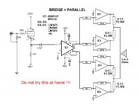
After some research, I found out that Jensen input transformer are 100$US which is a bit pricey to my taste so I was wondering if the following approach could be possible.
Most of you will see that I've merged two schematics posted on this forum.
Would it work or am I completely beside the track ?
Thanks for your help !
Most of you will see that I've merged two schematics posted on this forum.
Would it work or am I completely beside the track ?
Thanks for your help !
Attachments
- Status
- This old topic is closed. If you want to reopen this topic, contact a moderator using the "Report Post" button.
- Home
- Amplifiers
- Chip Amps
- Tube with Power IC Output Stage - JLTi