Creative??? I guess thats one polite way to describe it...
I steal a load of ideas then implement them incorrectly?
---
My earlier problem with limiters:
Any attempt to shunt an offending
gate toward cutoff (toward center),
had nasty side-effect to also shunt
the opposing gate into a complete
hard cutoff (much closer to cutoff
to begin with). And pull the drive
signal itself toward the offending
rail!
The correction circuit can only
pull inward, so had no power to
enforce common sense over this
inward pulling madness! Worse,
just fooled correction circuit
transistors to shut down too...
So thats why I have it all turned
inside out for the moment... Shunt
either gate toward cutoff (toward
rail), has side effect to turn ON
the opposing MOSFET. An inward
pull correction circuit can sucessfully
fight against this orientation of
unwanted error (through the mirror).
Also preventing unwanted shutdown
of the correction circuit. And pull
drive away from the rail too. (half
baked theory)
Is there is a better way to do all
this turned rightside-out? I havn't
figured anything that works yet...
---
Loftin White circuit is out of tune
now... You can graph +/-15mA in the
470uF bypass cap! I suspect the Mu
Follwer Gyro's self-centering resistor
R10 is too small value for plate load?
I measure big AC current leak here.
Inductor I had goten rid of earlier
might want to come back...
Or maybe I'll take another crack at
a real servo??? I suspect it didn't
work before for same reason as the
limiters. Maybe no problem anymore?
I have very positive impressions with your work and ideas.
Regards
I've stumbled upon the cause and possibly a solution to why the
crossing correction circuit hates any kind of soft or hard limiting.
Limiting actually works well if the driver isn't too low impedance.
A series resistor allows the limiter to work its magic. Of course
this is an unfortunate conflict with a drive of low impedance to
handle Miller when VDS<VGS...
I'm thinking to throw the limiter feedback direct to the plate.
So that its not fighting low impedance of the Triodlington's
emitter, nor confusing the crossing correction to shut down.
And lets us drive with low impedance, but feed back into a
higher one...
This is negative feedback, and may be outside the design
rule. But definitely not a linearizing feedback, nor feedback
that runs full time... Kicks in only to compress peaks in the
extreme situation.
I'll draw it up this weekend and see if it plays...
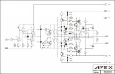
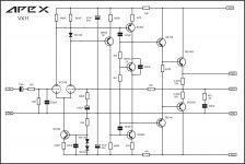
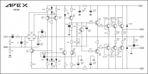
With quasi BJT output stage amp can be simple like this from 'Elektor'
Attachments
Last edited:
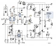
Preamp for Tube/Mosfet amp
Part list:
R1,R2-12k 2W
R3,R4-220R
R5,R6-680R
R7,R8-100R
R9,R10,R13-1M
R11,R12-3M9
R14,R15-10k
R16,R17-1k
R18,R19-10R
R20-680k
R21-470R
C1,C2,C3,C4-1uF400V MKP
C5,C6,C8-22uF/350V
C7-47uF/16V
C9,C10,C11,C12-47uF/350V
C13,C14-1000uF/16V
C15-47nF/100V MKS
C16-220nF/150V MKS
C17-100nF/63V MKS
D1,D2-ZF10V
D3,D4,D5-1N4148
D6,D7,D8,D9,D10,D11,D12,D13,D14-1N4007
V1-ECC88
Q1,Q2-BC546
Q3-IRF830
IC1-NE555
IC2-7805
LD1-RED
LD2-GREEN
RE1-5V2X1A
AC1-120VAC 100mA
AC2-9VAC 1A
Attachments
Schematic for preamplifier?
Hello!
Show the Schematic of this preamplifier!")
Best regards
Здраво Миле!
Ако си у могукности прикажи шему овог претпојачавача?!
Или кде може да се надје комплетни пројекат на интернрту?!
Унапред хвала!
Preamp can be use for drive output stage with high input impedance.
Hello!
Show the Schematic of this preamplifier!
Best regards
Здраво Миле!
Ако си у могукности прикажи шему овог претпојачавача?!
Или кде може да се надје комплетни пројекат на интернрту?!
Унапред хвала!
Last edited:
Hello!
Show the Schematic of this preamplifier!
Best regards
Здраво Миле!
Ако си у могукности прикажи шему овог претпојачавача?!
Или кде може се наки комплетни пројекат на интернрту?!
Унапред хвала!
Post 125??
Hello MiiB!
Where is the post 125?
How do I get it?
Thanks
The schematics is as I see it in post 125...
Hello MiiB!
Where is the post 125?
How do I get it?
Thanks
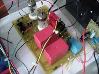
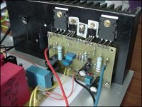
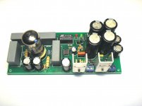
PCB this preamp with ECC88
Hello!
Show the Schematic of this preamplifier!
Best regards
Zdravo Mile!
Ako si u mogucnosti daj prikazi PCB za ovo pretpojacalo ili posalji ga na moj i-meil!
Unapred veliko hvala!
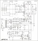
This is circuit of Counterpoint SA100.
Apex, this is an interesting circuit.
It doesn't have global negative feedback, unless I'm too tired to see it
Did anyone try it ? If so, how does i sound ?
This could be scaled up, dc coupled not a with a tube preamp coupled to a mofset buffer, its a true embedded hybrid. The dc servo is boosted do to the low open loop gain. Switch to a Higher gain tridode or pentode, higher rails, and this has good possibilities:
An externally hosted image should be here but it was not working when we last tested it.
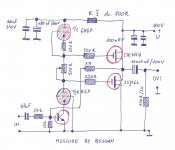
it is my version off Jeff Macauley's MOSCODE
And how much voltage swing can the tubes produce without distorsion from a 100V supply?
I have built a hybrid amp with a Tubecad Aikido front end married to a MOSFET power stage with BUZ MOSFETS. It is actually one of the best amps I have.
Tricky part is getting the bias to work easily. I ended up using the Pass burning amp bias circuit and it works awesome.
Tricky part is getting the bias to work easily. I ended up using the Pass burning amp bias circuit and it works awesome.
- Status
- This old topic is closed. If you want to reopen this topic, contact a moderator using the "Report Post" button.
- Home
- Amplifiers
- Solid State
- Tube/Mosfet 100W Hybrid Amplifier