Timing - some science
I dunno about you guys - but some of the threads have a lot of assumed knowledge attached to experimentation -
I know we have varying amounts of experience in here and I think I'll start putting a bit of science in here, because quite a lot of circuit design can be predicted by the maths
One of the things I like to do is strip everything back to the bare necessities. For example a soft start circuit. One would think, in some threads, that we're all out to design a "Power distibution protection system". Stick your amplifier with a plethora of protection circuits and "HEY PRESTO"....we're all happy.
Erm....not me - I'm designing an amplifier, not a science museum for protection systems - I dont intend to have any current limiting, I'm designing for optimum performance with enough elasticity in the design to take some trouble without burning out. Done it before in massive PA systems going up to many thousands of Watts. Down here in 200 Watt land, I'm pretty certain it isnt necessary all of the time. Some small DC protection may break out later in the design as no one likes rail Volts over there loads.
Using the soft start as an example - even the designers on this planet like to make these the most costly and complicated beyond what one would consider sane. Bruce Lee said of his art - strip out the waste and use ONLY what is necessary for maximum delivery. (Tao of Jeet Kune Do)
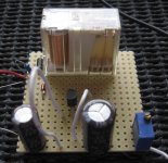
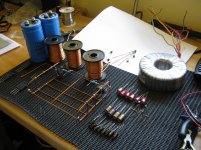
So here it is - my experimental soft start intended for this skeleton amplifier -- The components here are not necesserilly the ones of final choice - the solenoid may be bigger with whetted contacts and hermetically sealed.
However, no need to ignore the science behind it.
Timing a soft start is a bit of fun with physics and a simple bit of calculus. So I've done a simple graphic

And for those prefering a ready calc - in the zip is a ready made calculator with the formulas excel syntax
I dunno about you guys - but some of the threads have a lot of assumed knowledge attached to experimentation -
I know we have varying amounts of experience in here and I think I'll start putting a bit of science in here, because quite a lot of circuit design can be predicted by the maths
One of the things I like to do is strip everything back to the bare necessities. For example a soft start circuit. One would think, in some threads, that we're all out to design a "Power distibution protection system". Stick your amplifier with a plethora of protection circuits and "HEY PRESTO"....we're all happy.
Erm....not me - I'm designing an amplifier, not a science museum for protection systems - I dont intend to have any current limiting, I'm designing for optimum performance with enough elasticity in the design to take some trouble without burning out. Done it before in massive PA systems going up to many thousands of Watts. Down here in 200 Watt land, I'm pretty certain it isnt necessary all of the time. Some small DC protection may break out later in the design as no one likes rail Volts over there loads.
Using the soft start as an example - even the designers on this planet like to make these the most costly and complicated beyond what one would consider sane. Bruce Lee said of his art - strip out the waste and use ONLY what is necessary for maximum delivery. (Tao of Jeet Kune Do)
So here it is - my experimental soft start intended for this skeleton amplifier -- The components here are not necesserilly the ones of final choice - the solenoid may be bigger with whetted contacts and hermetically sealed.
However, no need to ignore the science behind it.
Timing a soft start is a bit of fun with physics and a simple bit of calculus. So I've done a simple graphic
An externally hosted image should be here but it was not working when we last tested it.
And for those prefering a ready calc - in the zip is a ready made calculator with the formulas excel syntax
Attachments
Likewise, hense my choice of output transistors. I'm pretty sure that 200A continuous & 400A pulsed current rating will be sufficientI dont intend to have any current limiting, I'm designing for optimum performance with enough elasticity in the design to take some trouble without burning out.

Nice to see things coming together over there
lol. I guess i'm used to the stuff, the only time i ever made a PCB was when i was 15, I used the schools stuffI hate using vero-bored --- yeeeeuch
Since then it's been vero all the way

By the way, what model scope is that Fluke of yours? I should be taking delivery of a PM3384A in a couple of days & i might need a manual lol. I should be ok with the thing after a bit of playing about i guess, always handy to have one available though.
Hunting for one on the net is like trying to find horse feathers
kit
Hey event horizon
It's the PM 3082 4 channel 100Mhz
I loved it and bought it off the cumpnee I woz working for because it was just so good to me.
I do have this dumb habit of collecting test equipment
not that it impresses the girls when you say "look at my huge equipment"
My transistors havent turned up so I cant do the next stage until they do
I keep checking the mail box -- I like goodie bags with components in
Hi Loopy
I can't understand why everything appears to be going right, anyway the PM3384A arrived today (should have been tomorrow with parcelforce 48 lol) & works a treat I actually found a manual for the PM3384B (which is exactly the same oddly enough ) so i guess i'm sorted.
I can understand why you like the 3082 if it has most of the functionality of this thing, i think the difference might be this beastie can operate as either a real time scope or digital storage at the push of a button. Compared to my Hameg it's like a Rolls Royce to a Reliant Robin.
I like goodie bags arriving to, i'm still collecting stuff. 20 Mosfets & 200 LEDs this morning, just waiting on a load of high power carbon resistors, zener diodes, schottky barriers & more mosfets... That is until i buy more stuff
Hope your transistors arrive soon fella, i'm looking forward to seeing the caged animal
E2A:- how can it be dumb to collect test gear?
I can't understand why everything appears to be going right, anyway the PM3384A arrived today (should have been tomorrow with parcelforce 48 lol) & works a treat
I actually found a manual for the PM3384B (which is exactly the same oddly enough ) so i guess i'm sorted.I can understand why you like the 3082 if it has most of the functionality of this thing, i think the difference might be this beastie can operate as either a real time scope or digital storage at the push of a button. Compared to my Hameg it's like a Rolls Royce to a Reliant Robin.
I like goodie bags arriving to, i'm still collecting stuff. 20 Mosfets & 200 LEDs this morning, just waiting on a load of high power carbon resistors, zener diodes, schottky barriers & more mosfets... That is until i buy more stuff
Hope your transistors arrive soon fella, i'm looking forward to seeing the caged animal
E2A:- how can it be dumb to collect test gear?
perfect
Totally right
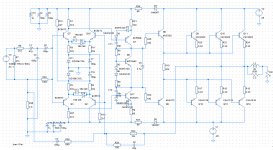
The secret is far too much scotch when sketching out the circuit - has been corrected - besides that experiment is long history, I'm dicking around with a different front end which is more sane.... in theory ....well....maybe......
I'll post the final schematic at the end when this thing has removed my eyebrows
I may be thick as a brick, but for the life of me I can't figure out how your input transistors have any idle current. The bases just dangle at the end of a cap each, with no path for DC.
Are you keeping that part as a trade secret?
Totally right
The secret is far too much scotch when sketching out the circuit - has been corrected - besides that experiment is long history, I'm dicking around with a different front end which is more sane.... in theory ....well....maybe......
I'll post the final schematic at the end when this thing has removed my eyebrows
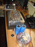
behold the magnificence
My driver trannys still havent turned up yet ---
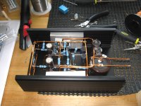
But I managed to get the headphone amplifier near finished - actually whilst waiting I got bored and had nothing better to do than build my new Quad Core PC and this -- what else am I sposed to do on a Sunday??........mow the lawn?
My driver trannys still havent turned up yet ---
But I managed to get the headphone amplifier near finished - actually whilst waiting I got bored and had nothing better to do than build my new Quad Core PC and this -- what else am I sposed to do on a Sunday??........mow the lawn?
Attachments
Sundays
Lmao, Sundays are like every other day of the week to me. Get up & put the kettle on, nip over the road & grab a paper. Cup of tea & begin waking up... Do the washing up & then do something after logging in to fleabay
I can actually see a good 20ft^2 of floor space in here since i started having a sort out yesterday, this continued today. The hifi sounds a bit different now, more how it should sound i guess without all the clutter I'm a hoarder but learning the error of my ways slowly
Interesting looking can amp, where's the circuit diagram?
Best of luck & have fun, Mark.
Lmao, Sundays are like every other day of the week to me. Get up & put the kettle on, nip over the road & grab a paper. Cup of tea & begin waking up... Do the washing up & then do something after logging in to fleabay
I can actually see a good 20ft^2 of floor space in here since i started having a sort out yesterday, this continued today. The hifi sounds a bit different now, more how it should sound i guess without all the clutter
I'm a hoarder but learning the error of my ways slowly Interesting looking can amp, where's the circuit diagram?
Best of luck & have fun, Mark.
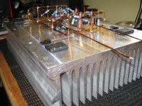
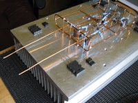
Skeleton Amp (SKAmp) Mk1 nearly complete
A Stereo 90W per chan into 8Ω version just to prove some points, tweak and meddle with; before I go head-long into building the two expensive mono-blocs
This is a nice big chunk of Aluminium but I am worried about positioning of the drivers
all BC550C input
ZTX873 and ZTX753 VAS
2SA1827 and 2SC4793 Drivers (As used in a Mark Levinson I own)
Attachments
Excellent news
Drilled any holes yet?
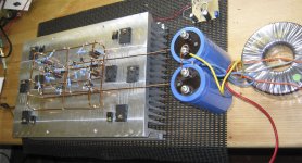
Yes they are now mounted and I am now coppering the drivers and output stage up
Speaker protect relay and soft start input to TX is being sorted now.
I Have 2x 120Ω 50W armoured resistors for limiting rails at first switch on and
a nice 8Ω dummy load once have set it up for idle
Attachments
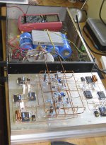
OMG it's ALIVE ! ! ! ! !
....**** it works !
After all this toil the damned thing works - w00t... as they say in gaming servers.
A fabulous 225W RMS into 8 static Ohms
I calmed it down a bit adding a 680Ω into the pos feedback to hold it back to 125W for now; whilst I get used to it and learn it's needs and idiosyncrasies. Map out all its V and I so I know where it stands.
Both quiesced nicely at 26mA
output DC residual offset is 2mV on one and 9mV on the other (no load)
so far that is all I have -- I'll do some noise and distortion measurements this weekend and once I'm satisfied I'll take it into the works labs and do a complete thermograph of it using our FLIR A40 camera.
I'm relieved - after spending a fair bit of £££ and time on building the beast
Attachments
Heh heh heh, it looks like some kind of Krypton Factor assault course with all the copper wire to climb through
I thought you might be making a stereo pair when i saw the way you were laying out the power transistors previously, nice to hear that it works & is stable Looking at the wiring you might get some benefit from fitting some decoupling capacitors nearer to the output transistors
Not a quible, just a suggestion
Well done fella, keep up the good work... By the way, what does the present schematic look like?
Bests, Mark.
I thought you might be making a stereo pair when i saw the way you were laying out the power transistors previously, nice to hear that it works & is stable
Looking at the wiring you might get some benefit from fitting some decoupling capacitors nearer to the output transistors Not a quible, just a suggestion
Well done fella, keep up the good work... By the way, what does the present schematic look like?
Bests, Mark.
- Status
- This old topic is closed. If you want to reopen this topic, contact a moderator using the "Report Post" button.
- Home
- Amplifiers
- Solid State
- Trying to build...an...OMG