stuff
Hey
I'm getting stuff from Farnell at moment
I had to repair and recalibrate my test equipment ready for the big push
I have to get the heatsink and hardware anodised next
PCBs I am having made in Birmingham
I'm working on a precision soft start and rail comparator to form part of the protection system.
Attachments
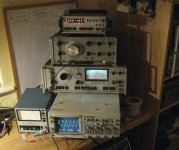
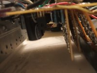
Keep it coming 
Looks like a nice 4 channel Fluke oscilloscope you have there, tasty.. Not sure of the rest of the stuff but it looks handy
I think i need to invest in a new scope myself, the power transformer in my Gould DSO decided to short itself out on the high voltage winding. That leaves me with just a Hameg HM203/6 Trying to find a replacement TX is like looking for little green men
On a different note it might be a good idea to sort out some of the protection circuits first, well you know...Lol.
Oh i know all about PCBs, it stuff i don't do. Nothing wrong with vero ROFL
Bests fella
Looks like a nice 4 channel Fluke oscilloscope you have there, tasty.. Not sure of the rest of the stuff but it looks handy
I think i need to invest in a new scope myself, the power transformer in my Gould DSO decided to short itself out on the high voltage winding. That leaves me with just a Hameg HM203/6
Trying to find a replacement TX is like looking for little green men On a different note it might be a good idea to sort out some of the protection circuits first, well you know...Lol.
Oh i know all about PCBs, it stuff i don't do. Nothing wrong with vero
ROFLBests fella
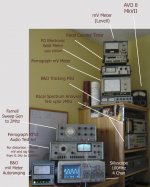
That's a very nice range of equipment. Far superior to my own offerings
I find it funny that stuff that doesn't get used for a while decides it just doesn't want to work any more. For instance, i needed to test a drivers parameters just before xmas & my Thurlby Thandar function generator decided it didn't want to know The frequency counter was fine though, anyway i bought a secondhand but as good as new 2MHz Tenma jobby, with built in frequency counter
I do have another function generator but it was no good for this job being 600 ohm output only, that's fine for amplifier testing as it's very low distortion.
Now lets see what you are going to do with this lot
I find it funny that stuff that doesn't get used for a while decides it just doesn't want to work any more. For instance, i needed to test a drivers parameters just before xmas & my Thurlby Thandar function generator decided it didn't want to know
The frequency counter was fine though, anyway i bought a secondhand but as good as new 2MHz Tenma jobby, with built in frequency counter I do have another function generator but it was no good for this job being 600 ohm output only, that's fine for amplifier testing as it's very low distortion.
Now lets see what you are going to do with this lot
 Or are you just knocking up something resembling a PCB layout with that wire?
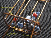
Hi
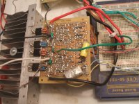
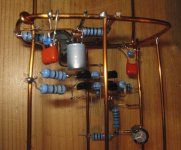
That’s an interesting way of doing point to point construction. What are the chances of the lacquer coated copper causing a short?
BTW, nice heat sinking hardware. Are those copper bars or white brass? I have a hunk of white brass, 8 X 16 X ½ inch that I may cut and use somewhere soon.
I do not think the method of construction is critical when you’re trying to build a bench amp. As long as the connections are sound, and layout is wise, it should work.
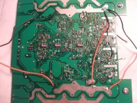
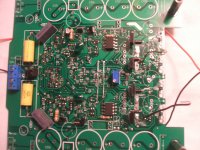
Don’t think you are limited to a simple circuit either using “homebrew” techniques. Check out the first version of my balanced amp I made over two years ago on vero-board…and it still works perfectly. (which honestly surprises the hell out of me. )There are 173 transistors in it.
The next version of this amp I’m currently working on is a bit more compressed. I have gotten everything to work up to the output transistors. That is the next step, for tomorrow, as I still have to prepare a bracket to mount the OPTs. Since I reached my goal for today and have commenced to drinking, I will not continue this evening. More on this amp is to come and I will start a thread for discussion on it. This is an intermediate model the next one will be even smaller. Most of the 0402 size resistors used could well be 0201 size. This latest version would be only but a dream if it were not for being able to ‘low tech style’ cheaply construct the complete circuit initially.
PS: contrary to what it may appear, there are no IC's in this circuit it is all analogue discrete. Actually there is one duel op-amp, a LM358 in a micro 8 package mounted just behind the blue pot, it is used to servo the LED in the two IL300 opto-couplers (DIP 8) that control the bias, but not technically part of the amplifier. Would have gone discrete here as well if I hadn't run out of PCB space!
That’s an interesting way of doing point to point construction. What are the chances of the lacquer coated copper causing a short?
BTW, nice heat sinking hardware. Are those copper bars or white brass? I have a hunk of white brass, 8 X 16 X ½ inch that I may cut and use somewhere soon.
I do not think the method of construction is critical when you’re trying to build a bench amp. As long as the connections are sound, and layout is wise, it should work.
Don’t think you are limited to a simple circuit either using “homebrew” techniques. Check out the first version of my balanced amp I made over two years ago on vero-board…and it still works perfectly.
(which honestly surprises the hell out of me. )There are 173 transistors in it.The next version of this amp I’m currently working on is a bit more compressed. I have gotten everything to work up to the output transistors. That is the next step, for tomorrow, as I still have to prepare a bracket to mount the OPTs. Since I reached my goal for today and have commenced to drinking, I will not continue this evening. More on this amp is to come and I will start a thread for discussion on it. This is an intermediate model the next one will be even smaller. Most of the 0402 size resistors used could well be 0201 size. This latest version would be only but a dream if it were not for being able to ‘low tech style’ cheaply construct the complete circuit initially.
PS: contrary to what it may appear, there are no IC's in this circuit it is all analogue discrete. Actually there is one duel op-amp, a LM358 in a micro 8 package mounted just behind the blue pot, it is used to servo the LED in the two IL300 opto-couplers (DIP 8) that control the bias, but not technically part of the amplifier. Would have gone discrete here as well if I hadn't run out of PCB space!
Attachments
Last edited:
Hi
That’s an interesting way of doing point to point construction. What are the chances of the lacquer coated copper causing a short?
BTW, nice heat sinking hardware. Are those copper bars or white brass? I have a hunk of white brass, 8 X 16 X ½ inch that I may cut and use somewhere soon.
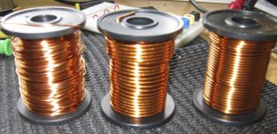
Yup I have about 5Kgs of copper which also increases Interference shielding as well as being very thermally efficient -
On the point of shorts -- it wont happen because white rubber grommets are inserted into the loops making the chance of a short near impossible. It would need to be a component breakdown to cause a short.
Banned
Joined 2002
Hi event - how are you
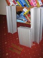
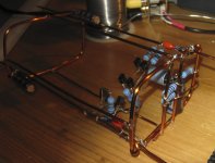
Yup !!! this amp is going to be a true skeleton - here's the cage for the front end and the heatsinks for the power bit -- no conventional PCBs will be used.
oh, nice tower heat sinks
Books on security for windows ? MCSE
what you think of the course ?Hey LoopyHi event - how are you
Yup !!! this amp is going to be a true skeleton - here's the cage for the front end and the heatsinks for the power bit -- no conventional PCBs will be used.
I'm fine thanks, i'm still gathering stuff from all over the world to get my pet project amps underway The list is thankfully getting shorter every day & cheaper to by some miraculous thing i fail to understand. I just keep finding stuff cheap Here's a little list
24 x 0.5C/W heatsinks, 24 x 0.6C/W heatsinks, 24 x MJ11030, 24 x MJ11033, 36 x MJ15024, 36 x MJ15025, 36 x TIP35, 36 x TIP36, 24 x S60SC4M (schottky barrier), 24 x 100BGQ015 (schottky barrier), 12 x 120,000UF 15V caps, 96 x 10,000UF 10V caps... I'm hoping i happen to have about 120 x 10,000UF 40V BHC caps here, but i haven't counted them yet as they are all over the place rofl... Oh did i mention there would be 6 identical amps, just incase youu thought it was me that was Loopy
I see what you are up to now, are you actually planning on using the "cage" as you call it on the finished amps? Or is this just to see how they'll perform & they might see some veroboard later?
I guess mine will go together on breadboard for testing & then onto veroboard for the actual thing. Never had any problems with the stuff as long as you lay things out in a tidy manner that mirrors the circuit design.
Good luck with it & have fun, i'll be following along whenever i'm on here.
Bests, Mark.
Yup I have about 5Kgs of copper which also increases Interference shielding as well as being very thermally efficient -
Are you worried about the copper tarnishing and forming an oxide layer on the surface?
Au plating would be nice.
 ...
... 
24 x 0.5C/W heatsinks, 24 x 0.6C/W heatsinks, 24 x MJ11030, 24 x MJ11033, 36 x MJ15024, 36 x MJ15025, 36 x TIP35, 36 x TIP36, 24 x S60SC4M (schottky barrier), 24 x 100BGQ015 (schottky barrier), 12 x 120,000UF 15V caps, 96 x 10,000UF 10V caps... I'm hoping i happen to have about 120 x 10,000UF 40V BHC caps here, but i haven't counted them yet as they are all over the place rofl... Oh did i mention there would be 6 identical amps, just incase youu thought it was me that was Loopy View attachment 164603
I see what you are up to now, are you actually planning on using the "cage" as you call it on the finished amps? Or is this just to see how they'll perform & they might see some veroboard later?
.
I didnt think that lot was intended for 1 amplifier - hehe
- if it were the power inlet cable may take a photograph of you as it vapourises at switch on . Did you forget to order a transformer or two?
I'm going to use this cage as a development mule - then refine the cage and have it produced professionally by precision metal people in copper.
It produces a faraday cage. I saw this method being used for a conical radar intended for the nose of fighter aircraft, and is all heavy gauge solid core. Should make the "solid core speaker cable" fanatics happy (not that they ever are, miserable lot). I'm hoping that with the amount of eventual copper - the reduced parasitics, hardly any capacitive properties without a conventional PCB might make a difference. Plus it gives some other development freedoms and flexibilities.
Last edited:
Really nice work!
It's big fun to see somebody doing an amp completely different - even different for a p2p guy
You would get this effect easier by using a metal enclosure; due to the smaller openings it is even more efficient. As you certainly know, electrical fields are usually not the problem, the magnetic fields are...but this should of course do not stop you to go ahead - it certainly looks great!
That's the usual breakdown of decades old gear. The caps age and get to a certain degree reformed when in use. If you don't use it for a little longer period - say one year - the cap impedance rockets (capacitance is usually ok) and cannot longer fulfill its purpose.
I know it's much work, but replacing caps after say 15 years is a good idea.
Have fun, Hannes
It's big fun to see somebody doing an amp completely different - even different for a p2p guy
It produces a faraday cage.
You would get this effect easier by using a metal enclosure; due to the smaller openings it is even more efficient. As you certainly know, electrical fields are usually not the problem, the magnetic fields are...but this should of course do not stop you to go ahead - it certainly looks great!
I find it funny that stuff that doesn't get used for a while decides it just doesn't want to work any more.
That's the usual breakdown of decades old gear. The caps age and get to a certain degree reformed when in use. If you don't use it for a little longer period - say one year - the cap impedance rockets (capacitance is usually ok) and cannot longer fulfill its purpose.
I know it's much work, but replacing caps after say 15 years is a good idea.
Have fun, Hannes
Did you forget to order a transformer or two?
I'm going to use this cage as a development mule - then refine the cage and have it produced professionally by precision metal people in copper.
It produces a faraday cage. I saw this method being used for a conical radar intended for the nose of fighter aircraft, and is all heavy gauge solid core. Should make the "solid core speaker cable" fanatics happy (not that they ever are, miserable lot). I'm hoping that with the amount of eventual copper - the reduced parasitics, hardly any capacitive properties without a conventional PCB might make a difference. Plus it gives some other development freedoms and flexibilities.
Actually i totally did forget to mention them yes. Well i have 12 x 500VA @ 26V AC (actually 0,22,24,26V) & 12 x 120VA toroids that'll be getting rewound by myself  To get the high voltage rails i'll make a monster 20KHz + charge pump, so i should be looking at +/- 70V & 36V rails (unloaded).
Nice to see an innovative idea with the cage
Just hope it doesn't end up trying to contain an animal Keep up the good work...Mark
Last edited:
Wont be just an Amp, Will be a great piece of art.
Hehe
yes, in part - like a skeleton clock - I'd like them to be intriguing to look at as well as beat Krell on sonic quality, drive character, load tolerance and musicality.
- Status
- This old topic is closed. If you want to reopen this topic, contact a moderator using the "Report Post" button.
- Home
- Amplifiers
- Solid State
- Trying to build...an...OMG