There's a lot of ideas about capacitors everywhere... many of them are foolishes
People say and believe a lot... and they do without test.... this is faith... faith means to believe without proof.... even if things are nonsense..the faith is there and people believe.
You should try the capacitors people say are good because, if you have the belief, and decide "not to use" the real special ones..the good ones..you will be thinking you will be loosing something in your sonics..when in the reality you will be only loosing some illusions.... so...follow your beliefs and go ahead...enjoy and be happy.... watch they use to be nice and shinny, expensive..boutique fashion things that i really do not believe can make all that difference.. at least my tests shown difference in between them are so small that we should not worry about them...many times they use tricks, as different capacitances.... not the same as informed....of course coiled capacitors (internally) are much worse than non coiled ones because inductance....so... ceramics may be better than some others... their construction, internal construction, may produce difference if coiled internally or not coiled..but if dieletric material is this one or other one.... fashion!
I have a lot of illusions too...they are so nice and so much better than the reality that i really do not care what is reality and what is not...i do think capacitors belongs to this universe of illusions, dreams and faith too...if we think golden capacitors will make sound golden and shinny..then we should go to them...if we believe that teflon (slips, skids) makes sound flow better..then go ahead.... if Panasonic Golden is better..than go ahead..if unobtanium is fine...be happy...this is what matters..to believe in something and to be happy... a hell to reality, sometimes real world is very deceptive.
Search in the internet for a paper called the "biggest 10 lies in audio".
Faith is nice...you know, we have some religions that says god is with us all time long.... even when we are in the bathroom? ... so.... have anything better to do?
regards,
Carlos
Last edited:
carlos,
you can't remember your dinner tonight ? then let me have those ! * *
*
You mentioned about the outer space ! have you seen those E.T. alien ? build an amplifier based on them !
ohh yeah, you can introduce any other amplifier that is near pure audio(same as source sounds) to me ? ^^ that will be the next project,hehe.
I'm quite young so i think i haven't heard those 60s-70s audio, but i think i will love it ! ( will give more comment after i built and listen)
about the heatsink, you mention about the spec of the heatsink, but what about it's mounting ? attached to which component (well... which component heats up easily ?)
About the soldering method of yours (tons of solder on top), i'm kinda interested in it ! what you use as the board material/type ?(base, which for the solders and component)
Regards,
Leong
you can't remember your dinner tonight ? then let me have those ! *
*You mentioned about the outer space ! have you seen those E.T. alien ? build an amplifier based on them !
ohh yeah, you can introduce any other amplifier that is near pure audio
(same as source sounds) to me ? ^^ that will be the next project,hehe.I'm quite young so i think i haven't heard those 60s-70s audio, but i think i will love it ! ( will give more comment after i built and listen)
about the heatsink, you mention about the spec of the heatsink, but what about it's mounting ? attached to which component (well... which component heats up easily ?)
About the soldering method of yours (tons of solder on top), i'm kinda interested in it ! what you use as the board material/type ?(base, which for the solders and component)
Regards,
Leong
Mount heatsinks into the output transistors..the bigger ones nearby the output
Use two blades instead of one... nice aluminium blades you can save from PC supply or obtain from Alcoa (exists in almost all civilized countries in this world)... have a blade and cut it using scissors, or garden scissors.... this gonna be your heatsink...fold them in the shape you like and attach them directly to the transistor, (a bolt and a nut, this way you gonna save time and money not needing insulators, spacers, washers and all that complication...that annoying stuff that fell down from our workbench and we go over knees to search for them...you may have only to avoid your heatsinks to touch ground because they have DC voltage on them and may short supply to ground..also you should avoid them to touch one each other.
Man....i have to watch schematic.... is this output using big ones?... i do not remember.
regards,
Carlos
Last edited:
ohh yeah, one more question.... I currently don't have any power supply at 36V, so i'm going to build one.
But i couldn't find an transformer which output is 36V, only found 35V is it suitable to use ?(with all the schematic same as 36V)
have any power supply schematic for this amplifier ? would love to have one to build.
Regards,
Leong
But i couldn't find an transformer which output is 36V, only found 35V is it suitable to use ?(with all the schematic same as 36V)
have any power supply schematic for this amplifier ? would love to have one to build.
Regards,
Leong
About to burn amplifiers...well..i understand this very well
I have expertise in this subject...i have built more or less 6300 amplifiers since i had 9 years old..... today i have 60 years old.... i use to say that but also i do not use to say how many exploded in my face....and exploded one third or them...more than 2 thousand failed because i had not knowledge and schematics i found in magazines where wrong.... i could not detect obvious errors when i was young..... but i have learned a lot...now i sniff the audio quality watching the schematic and values...yeah...i already can do that.
My name is destroyer x because i am an EXTRA DESTROYER of transistors.
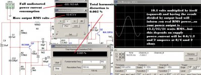
Not a good idea to use 12 volts...first because have to redesign the amplifier and uncle charlie will not do that... reason why is that no one that asked customized designs have assembled...there's a historical connection in between the ones wants customized and not to assemble ... the terrible "custom curse"
Output power will be very low if you try 12 volts..for sure i will not help you in that task..... because this kind of amplifiers, that uses a single supply, or a non simetrical supply, put out a little bit more than 1/4 of their supply voltage transformed in audio... and 1/4 of 12 volts is 3 volts.... a little bit more than 1 watt in 8 ohms is awfull...better to build a 2003 chip amplifier.
I see you are not skilled but you should burn your fingers and try...i am not having time anymore to be teaching ... so... sadly you will be half alone doing it...also i do think you will not build...because you're asking customized amplifier..already trying to change it to 12 volts..this is the sign that you will just talk and will not do it.
aahahahahahahah!
Images give you instructions...now move!...then you will have more attention from uncle charlie..first move and show pictures that you have made something.
regards,
Carlos
I have expertise in this subject...i have built more or less 6300 amplifiers since i had 9 years old..... today i have 60 years old.... i use to say that but also i do not use to say how many exploded in my face....and exploded one third or them...more than 2 thousand failed because i had not knowledge and schematics i found in magazines where wrong.... i could not detect obvious errors when i was young..... but i have learned a lot...now i sniff the audio quality watching the schematic and values...yeah...i already can do that.
My name is destroyer x because i am an EXTRA DESTROYER of transistors.
Not a good idea to use 12 volts...first because have to redesign the amplifier and uncle charlie will not do that... reason why is that no one that asked customized designs have assembled...there's a historical connection in between the ones wants customized and not to assemble ... the terrible "custom curse"
Output power will be very low if you try 12 volts..for sure i will not help you in that task..... because this kind of amplifiers, that uses a single supply, or a non simetrical supply, put out a little bit more than 1/4 of their supply voltage transformed in audio... and 1/4 of 12 volts is 3 volts.... a little bit more than 1 watt in 8 ohms is awfull...better to build a 2003 chip amplifier.
I see you are not skilled but you should burn your fingers and try...i am not having time anymore to be teaching ... so... sadly you will be half alone doing it...also i do think you will not build...because you're asking customized amplifier..already trying to change it to 12 volts..this is the sign that you will just talk and will not do it.
aahahahahahahah!
Images give you instructions...now move!...then you will have more attention from uncle charlie..first move and show pictures that you have made something.
regards,
Carlos
Attachments
Last edited:
kk, but nearby my house there aren't any electronic component stores, thats what killing me X.x
and malaysia's technology progress is abit **** that i can't find everything i want
i do online purchasses, thats why i'm pain in *** about the power supply !
hm.. since you said in the image(power supply) that it can be ranging from 23V-27V (or any X.x) can i use transformer of multiple output ?(2)
i only found few on the web i can buy :
one more addition problem, the MJL1302 on the website need long time for delivery, how can i get alternative similar to it ?(which can replace it, so that i can get it faster)
Is it possible to use MJL3281 into same place ? (not trying to alter the circuit, but...... desperate)
and malaysia's technology progress is abit **** that i can't find everything i want
i do online purchasses, thats why i'm pain in *** about the power supply !
hm.. since you said in the image(power supply) that it can be ranging from 23V-27V (or any X.x) can i use transformer of multiple output ?(2)
i only found few on the web i can buy :
Is it fine as my power supply ? I will start ordering tonight or tmrw morning, then start the project whenver the delivery is there, for sure, with some fascinating pictures for you !
one more addition problem, the MJL1302 on the website need long time for delivery, how can i get alternative similar to it ?(which can replace it, so that i can get it faster)
Is it possible to use MJL3281 into same place ? (not trying to alter the circuit, but...... desperate)
Last edited:
owww... that a headache, finding new transformer
Well... normal winding is slightly cheaper than toroidal, but torodial is more stable for audio application, isn't it ?RS | Transformers | Transformers | Chassis Mounting Transformers | Laminated Frame 230Vac Primary 75VA to 200VA (Multi Tapped) |10-5885
(100VA - 230Vac,50/60Hz - 2x0-20V)
RS | Transformers | Transformers | Chassis Mounting Transformers | Laminated Frame 230Vac Primary 75VA to 200VA (Multi Tapped) |10-5894
(150VA - 230Vac,50/60Hz - 2x0-24V)
RS | Transformers | Transformers | Chassis Mounting Transformers | Laminated Frame 230Vac Primary 75VA to 200VA (Multi Tapped) |10-5901
(200VA - 230Vac,50/60Hz - 2x0-20V)
RS | Transformers | Transformers | Chassis Mounting Transformers | Laminated Frame 230Vac Primary 75VA to 200VA (Multi Tapped) |10-5903
(200VA - 230Vac,50/60Hz - 2x0-30V)
http://malaysia.rs-online.com/web/search/searchBrowseAction.html?method=getProduct&R=0503938
(200VA - 230Vac,50/60Hz - 2x0-24V)
Toroidal:
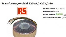
RS | Transformers | Transformers | Toroid Transformers | Toroidal 230Vac Primary 15VA to 1000VA
(120VA,2x25V,2.4A)
RS | Transformers | Transformers | Toroid Transformers | Toroidal 230Vac Primary 15VA to 1000VA
(160VA,2x25V,3.2A)
RS | Transformers | Transformers | Toroid Transformers | Toroidal 230Vac Primary 15VA to 1000VA
(160VA,2x30V,2.667A)
RS | Transformers | Transformers | Toroid Transformers | Toroidal 115-230Vac Primary 15VA to 1000VA
(160VA,2x30V,2.667A)
Last edited:
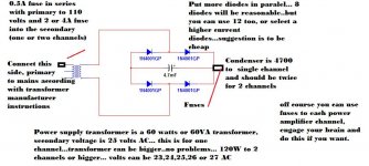
These transformers will be good...i do like the toroidal one
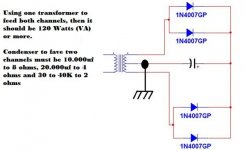
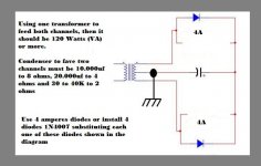
You will need one transformer to each channel or will be limited to 8 ohms operation....if you want to use a single transformer and obtain good power, then order a 120W unit.
attached diagram to three wire secondary.
regards,
Carlos
You will need one transformer to each channel or will be limited to 8 ohms operation....if you want to use a single transformer and obtain good power, then order a 120W unit.
attached diagram to three wire secondary.
regards,
Carlos
Attachments
o...o..... wait, i think i'm missing something, quite a big thing...... the schematic is a monolithic amplfier ? (well.. i only see one output)
OMG i need to double up my other items.... is still good that i haven't brought it....
OMG i need to double up my other items.... is still good that i haven't brought it....
Sorry for my weak recognisation:
the speaker is connected to "OUTPUT" (in the schematic)with positive and negative with ground ?
The input should connected to "INPUT" (in the schematic) with signal and ground/shield to ground ?
About Trust
Some videos:
Trust cap coupled, no prejudices! - YouTube
Trust 40V - YouTube
Trust Clipping lamp - YouTube
Trust, the most delicious Dx Amplifier! - YouTube
regards,
Carlos
Some videos:
Trust cap coupled, no prejudices! - YouTube
Trust 40V - YouTube
Trust Clipping lamp - YouTube
Trust, the most delicious Dx Amplifier! - YouTube
regards,
Carlos
Come on guitar...now you want to modify my baby?
This is not nice...in special because bridge is something i hate...here you have what i think about in three languages:
Do not connect bridge mode - YouTube
Amplificador 400W, no use puente - YouTube
Não use circuitos em ponte - bridge - YouTube
By the way my dear ... conversation about modify my tested amplifiers are something i do not like...so...bye bye and good luck.
I see... supply in paralel...well.... bridge rectifiers in paralel
is another story...anyway, you are starting to think about customize..this is a problem....you will not do anything..this is what statistics have shown me these last 7 to 8 years...we gonna see if i am right or wrong...i hope you are out from that statistics.
Well...i have group buy running in other foruns (soon we gonna have here too) and questions to answer..i will give a break and let you build something..then i will land earth once again to watch pictures of your progress...of course if not modifying my baby..because if tried to modify...then i will leave you alone doing this.
We humans...we have our own mind disturbances..our long time neurosis... we have our limits of acceptable or not acceptable...something from the dawn of civilization..from the caves... the ancient Neanderthal and Cro-Magnon...there are frontiers we do not accept people cross, we perceive as invasion and this means war.... change my circuit is something i really dislike.
This thread has all you need..also Greg Erskine site has all you may need about Trust...so..you have all the tools to proceed.
Be happy, good luck to you my dear..uncle charlie gone!
bye!
Carlos
Attachments

Last edited:
LOL well..... i kinda hate those people like as in your statistic you mentioned, so...... action is the best way ^^
hm... just some question.... according to power supply in your diagram.(3 wire secondary)
if i'm not wrong(well... i don't have a naked transformer), it will have 4 leads(for 2x30V).
How should i connect 4 leads into 3 wire secondary as per your diagram?
negative/ground is connected to chassis or power source ground?
if i'm not wrong, connect in that way means in series, mean add up 2 value (eg. 2x30v=60v), then i should get lower rating such as 2x18 ?
and the amplifier should connect to which point(Vcc/B+) on the diagram of yours ? (kinda hate myself for being so....... UN-knowledgeable)
really need these information in order for me to work out the power supply....
Attachments
Last edited:
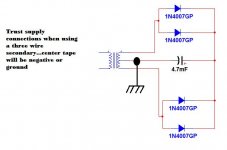
Connect black and yellow together.
then you will have a center tap constituted by this union of black and yellow wires.... will result a three wire secondary.
the result is that black and yellow joined together will be connected to chassis, the ground, and will also be the negative to the power amplifier.
Other two wires will go to diodes, two four amperes diodes (or more) will be interesting... then connect your condenser.... voltage rectified and filtered will be 30 alternated volts multiplied by 1.41, and this may result aproximatelly 42 volts and this fine to Trust amplifier.
Well man... seems you have a very little know how... be carefull or you will repeat my destiny..will blow your amplifier and in a matter of 49 years you will be creating amplifiers in some year 2060 forum... the future.
regards,
Carlos
Attachments
Last edited:
- Status
- This old topic is closed. If you want to reopen this topic, contact a moderator using the "Report Post" button.
- Home
- Amplifiers
- Solid State
- Trust, the most delicious Dx Amplifier