When I eventually get mine I'll initially be looking at the power supplies to the TL072s
The opamps look to be JRC 4580 or did you mean TL072like devices?
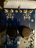
Its my own mistake, I was assuming that the board whose picture is shown in part in post #536 was the one you were using. But what I wrote about TL072s applies as much to any other opamps in terms of them needing clean supplies. I'm not familiar with the drive capabilities of JRC4580s though.
My board is stuffed into a chassis, so it would be a pain to take a picture of the bottom of the EVM. Here's the User's Guide
http://www.ti.com/lit/ug/slou441/slou441.pdf
On page 11, bottom image, the soldered jumpers are J22 thru J24 near the left side of the image. As delivered, the jumpers are all soldered in place. The instructions are are pages 6 - 10 for the various combinations.
They are pretty small. When the jumpers are removed, the output will pass through the four 1500uf caps on top of the board, so no need to replace the jumpers with coupling caps. Perhaps someone can post a picture of the bottom of the EVM.
One other thing. In SE mode, the gain is only 21.5db, not the 27.5db gain you would get in BTL mode. This may or may not be an issue, depending on the miniDSP you are using.
Mike
I'm thinking of pairing the TPA3255 with this fanless 200W meanwell power supply (48V). [POWERNEX] MEAN WELL NEW UHP-200 200W Slim PFC Switching Enclosed Power Supply | eBay
Other than not being able to get the full power from the TPA3255 are there any other consequences?
That PS is 94% efficient, and should work great with tpa3255. You'll have a very green amplifier! If you're not driving a subwoofer or other challenging load, you won't miss the extra amperage. It probably won't allow you to adjust over 51V but that's enough. tpa3255 published specs were measured at 51V. Also, it will probably trip overcurrent everytime you power on, but it recovers automatically. You may hear some extra restart 'ticks' from the PS, but again, nothing to worry about.
Consider ordering from mouser.com rather than the vendor on ebay. I've bought from both, and you'll get it from mouser a lot sooner at around the same money.
I am planning to use a LRS 350-48 SMPS with the TPA3255 EVM at 40V. If I want to place a 10K uF electrolytic cap near the EVM terminals, for bettering the bass, what should be done?
Already the SMPS will trip overcurrent at startup, will the cap worsen this? Can it be cured by placing an inductor before the 10K cap, and if so what should be the value of the inductor?
Already the SMPS will trip overcurrent at startup, will the cap worsen this? Can it be cured by placing an inductor before the 10K cap, and if so what should be the value of the inductor?
Big caps parallel to smps output are generally a bad idea.
Loop transient response will be slowed down, at a certain point stability may be affected. All you will get is additional stress inside the smps and no better bass response at all.
A proper designed smps keeps output voltage constant under all your load conditions - so nothing can be gained by caps rolling.
voltwide, I've tried telling him on numerous occasions that it's a terrible idea, but his heart is set on it. If anything, a smallish cap followed by an inductor (tuned to filter say >10 kHz) would benefit more to passively knocking out switching hash. Le'shrug.
Also, just leave the amp at 48V! Gives you more headroom before clipping if nothing else, especially if you're not affecting the gain.
Also, just leave the amp at 48V! Gives you more headroom before clipping if nothing else, especially if you're not affecting the gain.
Already the SMPS will trip overcurrent at startup, will the cap worsen this?
Sure - it'll overcurrent for a longer time with more capacitance.
There's no cure for the overcurrent when fitting the inductor. Rather the L serves two purposes a) reducing the output ripple and b) giving the feedback circuitry of the SMPSU an easier load (meaning better stability in use). Try using an air-cored inductor (the kind often found in passive speaker crossovers) of around 200uH.Can it be cured by placing an inductor before the 10K cap, and if so what should be the value of the inductor?
You mentioned putting a LC after the SMPS, to filter out the HF which the SMPS may send. Can you please tell me the values of L & C to use.DPH, what you say is actually true.
Being old school, I have a fixation on the large cap bank that I see in Class A & B Amps, which supposedly give the bass response.
So this idea of caps doesnt seem to go out of my head, when it actually should")
There is a big difference between old school transformer design and smps: With smps the rectification takes place on the primary side and consequently the bulk cap is the cap on the primary side. Be aware that 100uF charged to 300V store the same energy as 10.000uF charged to 30V. So whenever you want to "ugrade" smps bulk storage, the primary cap is the way to go.
So where does the "lumpy DC" that the SMPS chops accordingly come from? Mains side is only getting supplied every 1/120th of a second (or 1/100th). You definitely want a good amount of energy stored in the main side capacitor.
SanjeevM -- I wish I knew the switching frequency of the Meanwell module, but I haven't plopped it on an oscilloscope to check. A quick Google search with "LC output filter SMPS" will find you pages such as this: Designing Second Stage Output Filters for Switching Power Supplies | Analog Devices
Which will allow you to figure out exactly what sort of inductor you need and determine how much attenuation you want at, say, 10 kHz. Just remember your final capacitor (C2 in aforementioned link) in the form of two paralleled 4700 uF Cornell Dublier SLPX (at least on my boards) on the TPA3255 EVM board. Good luck!
Last edited:
 Please do NOT quote the post right above yours.
So where does the "lumpy DC" that the SMPS chops accordingly come from? Mains side is only getting supplied every 1/120th of a second (or 1/100th). You definitely want a good amount of energy stored in the main side capacitor.
Yes, you need sufficient energy stored, normally its sufficient to survive a single missing cycle of mains (so 20mS hold-up max). Adding extra uF though provides no benefits to the output side, except in cases of extra missing mains cycles.
- Home
- Amplifiers
- Class D
- TPA3255 - all about DIY, Discussion, Design etc