So load has 10k to gnd. The 10k/10k divider for single rail use of opamps ?
good morning irriebo

at the opamps i measure folowing with psu 24 = > regulator.....22,32V
GND is at the input psu socket metal outside
pin 1,2,3 (output A, Input A -, Input A+) = 11,16V
pin 4 = V- = 0,003V
pin5,6,7 ( INput B +, Input B-, output B) = 11,16V
pin 8 = V+= 22,32V
so the op amps have no gain ? - so it is configured as buffer?
chris
The only real problem people reported is that the amp switches off, for example it can't put out ~20 watt into 4 ohm load, if I read tables correctly. That seems a little low.
correct !...thanks

What's the problem in detail, does it sound bad in any way?
welcome doctor !
you measure Vdc, gain would be Vac ?
Half DC is zero level around which single rail opamp has room to put out positive wave and negative wave.
thank you.......... i am ...

...different PSU ...same result...
Hi again
i try my rigol DP832 to look closer to the amps behave at 4 ohms load.
but its just the same result. about 3 min the channel R switched off.
several time the amp (after recooling) is not reacting to the switching on--> no signal on both channels ?
what i forgot to report is that one coil is alwas hotter than all other 3 coils.
thats the reason in the table i write down the hottest. in brackets there are the others.
have a nice day...
chris
Attachments
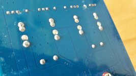
Soldering to pcb of coil (s) is ok ?
Switch off just as fast with like 100Hz to 10KHz sweep ? Or 200Hz to 10KHz, or does amp switch off with 1V 1KHz sine too ?
the soldering looks ok....see pic
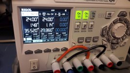
in running time a can see on the rigol psu the power consumption.- both channesl working...(pic2) one DMM is mearuing the voltage at channel R, the other is measuring amps at channel L.
if the amp is not willing to do somehting i can see just one channel or no channel is working.
the amp is after this shut down in a "strange mode", because the amp do not care.......with or without input from freq. generator he is switching on but no signal on ch L+ R....
its strange too that at every case i changed from 8 to 4 ohms load and i switched on the first time i got the error led blinking!
thanks for your help...
chris
Attachments
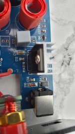
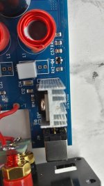
...about the IRF 9530.....closed to the input voltage socket...
i did 2 pics from the upperside...
......hmmm... no idea...
its written at page 23 #230... it was an idea. but until now nobody really checked.
this willbe a task for tomorrow for me...i try my best.
i did 2 pics from the upperside...
......hmmm... no idea...
Attachments
R41=2400....236ohms and R40 = 4301.....3020ohms ??
if i use the calculator:
with this values R1= (R41)= 236 and R2=R40= 3020........i get : 17,25V
so what ????
chris
Hi Chris,
A "4301" marked resistor has, as you already assumed, a 4 - a 3 - a 0 and 1 more zero in resistivity. Thus, 4300 Ohm (4K3). Why do you measure 3020Ohm? Because you measure "in-circuit", hence, with other possible ways for the measuring current to run. You already know you have a 240 Ohm resistor connected to the 4301 resistor and that 240 Ohm resistor is connected to the output of the LM317. Very likely you have a resistive load on the LM317 output. Thus, when you believe you are measuring the value of the 4301 resistor only, you at the same time have a secondary current flow-path through the 240 Ohm resistor and the resistance at the LM317 output.
From my calculations of the LM317 output voltage, this resistor is close to 4K3 as it should be - only the input voltage is too low and you have a saturation problem.
Last edited:
Hi Chris,
A "4301" marked resistor has, as you already assumed, a 4 - a 3 - a 0 and 1 more zero in resistivity. Thus, 4300 Ohm (4K3). Why do you measure 3020Ohm? Because you measure "in-circuit", hence, with other possible ways for the measuring current to run. You already know you have a 240 Ohm resistor connected to the 4301 resistor and that 240 Ohm resistor is connected to the output of the LM317. Very likely you have a resistive load on the LM317 output. Thus, when you believe you are measuring the value of the 4301 resistor only, you at the same time have a secondary current flow-path through the 240 Ohm resistor and the resistance at the LM317 output.
From my calculations of the LM317 output voltage, this resistor is close to 4K3 as it should be - only the input voltage is too low and you have a saturation problem.
thanks............noob failure
you are right...
next test will be with about power suplly 28V
...28Volt power supply- amp is working!...
Hello again...
final test during this long weekend .....a push as good as i can...
the amp is working at 28V with 4 ohms load- about 27Watt each channel during 24 min...then i stopped because of high temperatur 84°C -HEATSINK..... i think the amp could go ahead.....see report.
Irepeat the test with 28V and 8ohms. but its the nearly the same as the original psu, more heat.
the regulotor is working now.
Pin 3 input pin4 OUT PIN 1 adjust 27,72 23,74 22,48
Attachments
Last edited:
summary
To keep the original psu with 24 V -23,7 (the psu is strong . i have to change the resistor near the LM317 from 4300 to 3600. then is should get about 20V output regulated.
that means a 2k ohm /2k2 resistor in parrallel to the 4300 resistor should give me about 3600ohm --> so about 20 volt out from the LM317
LM317 Voltage Calculator | REUK.co.uk
thanks for your help...
the connection from the cool modding with the ceramic resistor is working fine. at the 4 ohms test i get finaly about 37°C at the buttom plate at the spot of the chip. few centimeters away about 33°C
...to be continued...
chris
Last edited:
Hi Chris,
You need a bit more sleep: a 2K or 2K2 resistor in parallel with the 4301 resistor does not give you 3K6.
Try the calculation again tomorrow.
Good night Chris!
morning
yes its one zero more!
20k or 22k ohms should fit...
Parallele Widerstaende Rechner parallel R1 und R2 Widerstands-Berechnung Parallel-Schaltung Widerstand berechnen Wert E-12 Reihe berechne Gesamtwiderstand Parallelwiderstand - sengpielaudio Sengpiel Berlin
doing lots of things (kids , garden,.......) in parallel and audio calculation....is not ok...
You can bypass the two of them (4301+20k) with a 10 or 22uF low esr capacitor, just because you are soldering there anyway and it should lower noisefloor 317 around 20dB.
I think I would also put a small value bypass, 100nF??, under the rubycons, to reduce potential hf smps noise to opamps a tiny bit, some ends up at tpa input and might warm the coils
I think I would also put a small value bypass, 100nF??, under the rubycons, to reduce potential hf smps noise to opamps a tiny bit, some ends up at tpa input and might warm the coils
You can bypass the two of them (4301+20k) with a 10 or 22uF low esr capacitor, just because you are soldering there anyway and it should lower noisefloor 317 around 20dB.
I think I would also put a small value bypass, 100nF??, under the rubycons, to reduce potential hf smps noise to opamps a tiny bit, some ends up at tpa input and might warm the coils
Hi irribeo
thanks for your inputs.
yes i will check my sortiment, low esr 22µ elko should not be a problem
i should have some new 1µF WIMA MKS
and some Tantal drops.
thx chris
Last edited:
- Home
- Amplifiers
- Class D
- TPA3250 somebody is listening?