...maybe this helps...
XLO Reference Recordings Test & Burn-In HDCD-Elusive Disc
Track 2 In-phase
Track 3 Out-of-phase
AN "IN-PHASE/OUT-OF-PHASE" RECORDING OF THIS TYPE IS THE VERY BEST TOOL YOU CAN USE TO MAKE SURE YOUR SPEAKERS ARE PROPERLY WIRED AND PROPERLY PLACED. IT CAN EVEN HELP YOU TO IMPROVE THE ACOUSTICS OF YOUR LISTENING ROOM!
---FX502s pro PSU measurments....
...so i am back,,,,i am hungry for some audio....
I did a test with both psu.
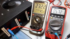
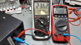
the PSU is able to push 5,65A @23,13V for 10min. it gets hot on the side more then on the top -about 60°C. after 10min i stopped.
23,13 x 5,65 = 130Watt
so the power is better than expected or recommended by the manufacturer
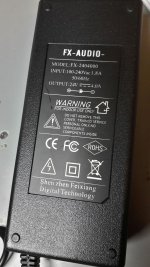
FX 502 pro is labeled with 24V x 4 Ampere = 96WATT.
so the psu is fine !
cu
chris
...so i am back,,,,i am hungry for some audio....
I did a test with both psu.
the PSU is able to push 5,65A @23,13V for 10min. it gets hot on the side more then on the top -about 60°C. after 10min i stopped.
23,13 x 5,65 = 130Watt
so the power is better than expected or recommended by the manufacturer
FX 502 pro is labeled with 24V x 4 Ampere = 96WATT.
so the psu is fine !
cu
chris
Attachments


...good evening..frequency response and temp test
Hi
i did a frequency test and a temp test. the frequency test is done by 2 x DMM (but not true RMS)
the temp test was done with closed case but screws out. after every measurement i closed again the top case to simulate real situation.
the modding is done with the ceramic resistor to get the temp to the buttome case too. additionlly to the ceramic 5,1mm i add 4 x pcs of isolator for TO220. so the contcat is much better to the buttom plate:
80hms load each channel with original psu - about 13Watt each channel
look at the pdfs...
chris
Hi
i did a frequency test and a temp test. the frequency test is done by 2 x DMM (but not true RMS
)the temp test was done with closed case but screws out. after every measurement i closed again the top case to simulate real situation.
the modding is done with the ceramic resistor to get the temp to the buttome case too. additionlly to the ceramic 5,1mm i add 4 x pcs of isolator for TO220. so the contcat is much better to the buttom plate:
80hms load each channel with original psu - about 13Watt each channel
look at the pdfs...
chris
Attachments
Last edited:
my summary of this tests...
The original psu and amp is designed for about 13 watt each channel for more 90min listening.
the modding with the ceramic under the TPA chip is needed.
the psu is designed for max 5,5 Amps ( 2 channels with about 2,8 amps) as you can sse in the previous psu test- in the sweep test i can see just 2,2 amps pera channel but....
so my suggestion is that at the test with 4 ohms load at the amp on each channel i get undervoltage.
why the amp is not give error led in every case i do not know.
...another test...i need help...
my suggestion was that the IRF9530 is for overvoltage protection as mentioned in page 23 #230.
i tried a test with 8ohms load and sweep (10Hz- 25khz) but with 2 Vrms input on both RCa channels. i got after 6 minutes a strange smell ! - the IRF9530 heated up to about 100°C!!!
i stopped and coll the chip as fast as i can. every other test i could see a rapid increase of temp at the IRF 9530....but why???
after coooling down to 21 °C everything a made a normal test with 8ohms load and 1Vrms input again. i got normal settings like in the other tests (see pdf 2 posts before). so the chip work fine.
any ideas???
Attachments
as zek wrote...it is not easy...
...belive me there is no room for that.the original "heatsink" is 50mm long ,25mm width and a high about 15mm. 7 fins with approx 1,5mm. so its a kind of 5K/W heatsink.
use the cearmic resistor on the buttom of the pcb and get your "additioally" heatsink from the housing of the amp.

 Respect !!!
dimension ?
dimension ?
Before it was sawed it was 90х50x26(h) mm. Now the capacitors do not touch the heatsink. But they still heat up a little, apparently through the board.
By the way, the height of the original heatsink was 15 mm only. And the new one is much larger even after sawing.
on the pic it looks like you can mount it on the alu housing on both side?
yes , no?
No, no contact to housing. It's not easy to do, 'cause the top and bottom covers move.
Last edited:
Heatsink gets heat from mainheatsink=pcb, you improved connection to pcb ?
Measured temperature of (purple) heatsink doesn't tell much when connection to pcb is not good, what is temperature of pcb below chip or ground next to chip or on negative pin capacitors ?
Mosfet circuit used by FX isn't on 3250 evm I think, MCU isn't on 3250evm either, so FX tried to make own protection maybe ???, how to know fault/protection tripping is indeed tpa3250 it might be FX own circuitry ???
The 0V problem has more to do with pcb ground layout than with external psu, seems like external psu is powerfull enough for the Sonus speakers (=easy load), or doesn't seem reason the FX reaches protection.
- Home
- Amplifiers
- Class D
- TPA3250 somebody is listening?