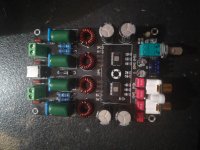
I decided to swap the incredibly shitty pot on my amp board for a better one.
And I managed to somehow destroy it. One channel is still playing nicely, without the noise of the original pot, but the other channel is just noise and no sound.
I imagine I damaged the pcb when prying off the old pot. I think the connections are on the top of the board, where they can't really be seen so well. Can someone with a better knowing of this board suggest where I should try and solder a jumper wire first?
Attachments
nichicon capacitors
Hi,
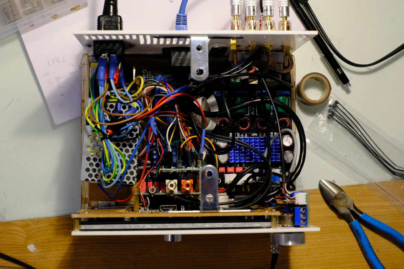
Sorry for digging this post, but I have the same XH-M590 board, which is indeed quite good. I wanted to follow FauxFrench advice and change the capacitors, but could only find 50V Nichicon Glod Tune 2200uF. My problem is that those are really big and don't fit in the existing capacitors place. How should I mount them ? Should I use a daugher board to house those capacitors and use 8 wires to solder it to the XH M590 board ?
Hi,
Sorry for digging this post, but I have the same XH-M590 board, which is indeed quite good. I wanted to follow FauxFrench advice and change the capacitors, but could only find 50V Nichicon Glod Tune 2200uF. My problem is that those are really big and don't fit in the existing capacitors place. How should I mount them ? Should I use a daugher board to house those capacitors and use 8 wires to solder it to the XH M590 board ?
XH-M590 Many postings ago I was asked which TPA3116 board I found was the best. I made a brief study from photos of different boards and concluded that the XH-M590 board seemed to be one of the best ( KYYSLB DC12 24V High Power 100W*2 TPA3116D2 Digital Power Amplifier Board XH M590 Home Audio Amplifier Board 2~8 Ohms|Amplifier| - AliExpress ): Good output filter components, dual TPA3116 chip with a large heatsink fastened with a screw, decent power line decoupling with possibility for upgrade, good connectors and film input capacitors.
An issue was that the XH-M590 board exists in two version of which a less attractive version has two smaller heatsinks glued to the TPA3116 ICs and uses non-standard squared power-rail decoupling capacitors. I managed to find the version I preferred and ordered it on 30.11.2019. Tracking the parcel with the board went well until I was told (E-mail) that the board had just been delivered to me which it had not. I investigated the fate of my parcel but found nothing precise and in the end I kindly got reimbursed. I forgot about the board. But, Monday 8 June 2020 the board somehow made it to my mailbox, in original packing, after more than 6 months!
Now I will briefly describe my first test results because the board actually is one of the best considering the price (from a bit above 10 Eur with sending costs).
The board layout is neat and the PCB of good quality. The mounting of components on the board is quite good, and I only re-did a few solderings.
For power-rail decoupling, four 470uF/50V capacitors are used. While 50V voltage rating is unnecessarily generous, 4x470uF is not much if benefit is taken of the dual chip design with low impedance loads. Luckily the initial decoupling capacitors are physically rather short and at ”fat” such that there is good space for larger decoupling capacitors. After a very brief check with a 12V supply that the initial board functioned, the initial decoupling capacitors were changed to four 2200uF/35V Nichicon capacitors. If you use low impedance speakers, the DC input connector (for power supply) may be bypassed by supply wires soldered directly to the terminals below and the reverse-polarity-protection diode short-circuited.
With a 20V/24V power source, the board plays very well. Good vocals and bass. The gain is for most use (too) high and without music, I believe I can hear a bit of hiss with the volume potentiometer in mid-position. I will reduce the gain to 20dB and mount two 4K7 resistors on the potentiometer output which should certainly remove any hiss.
From my test of the board, I can only recommend it as one of the best for a moderate price.
For less experienced members, such a basic board (stereo) without a buffer amplifier at the input and no sophisticated control of activate/mute functionality can be an important advantage. In case a basic board does not function well, the circuit implemented is close to the circuit recommended in the datasheet. The moment 2.1 features (filters), pre-amp circuits, numerically controlled input selection circuits and in particular BlueTooth circuits are included, much goes wrong in these circuits and we on the forum have no idea how these circuits are designed and implemented. Therefore, it is difficult to help you find errors in such complex boards. Keep it simple and use basic boards. If needed, use separate boards for filters, pre-amp circuits and BlueTooth – this way we can decide which boards work and which not.
I would use four 470uF low-ESR capacitors IN THE BOARD and add an intermediate board (between the power supply and the XH-M590 amp board power terminals) with further two 2200uF Nichicon Gold Tune capacitors. Short-circuit the polarity protection diode. You need some decoupling with very short leads (on the board) because the switching spikes are of high frequency. Connecting Gold Tune capacitors through wires as replacement of the capacitors on the board will leave too high ESR at high frequencies.
Last edited:
You have a possibility. First, if your input impedance is 1K, remove the two SMD resistors. Next, the RCA input connectors are located next to the red input signal coupling capacitors. Make small wire-jumpers from the RCA signal terminals and to the relevant two red input signal coupling capacitors. Eventually, mount two 22K resistors below the RCA connectors, from the signal terminals and to ground. That way you do not have a very high input impedance and noise sensitivity.
Thank you for your help, but trying to umderstand what you meant, I decided to just buy new amps.
€ 15,24 38%OFF | TPA3221 Digital Class D Power Amplifier Board Module 100W + 100W High Power Amplifier
TPA3221 Digital Class D Power Amplifier Board Module 100W + 100W High Power Amplifier|Amplifier| - AliExpress
2 of those, and volume control through minidsp. Should be a lot better than any 3116's I think")
€ 15,24 38%OFF | TPA3221 Digital Class D Power Amplifier Board Module 100W + 100W High Power Amplifier
TPA3221 Digital Class D Power Amplifier Board Module 100W + 100W High Power Amplifier|Amplifier| - AliExpress
2 of those, and volume control through minidsp. Should be a lot better than any 3116's I think
I have one of these TPA3221 boards. In my opinion it has a very good sound. The chip is from the more sophisticated TPA32xx family.
My only problem was a fault in the start up circuit. That left quite some start-up noise. A very small transistor was aligned poorly compared to the PCB pads. Described in a TPA3221 thread.
My only problem was a fault in the start up circuit. That left quite some start-up noise. A very small transistor was aligned poorly compared to the PCB pads. Described in a TPA3221 thread.
I ask you to think about this. I am interested in ultrasound experiments. Can such an amplifier, equipped with TPA3116D2, amplify in good conditions, a signal for example 50KHz, if the integrated circuit is set properly, to work on the frequency of 1.2 Mhz ??
The output filters are calculated for a cutoff frequency of 100 Khz, so that there is no real attenuation of the 50 Khz signal.
What do you think ? Is this idea feasible?
The output filters are calculated for a cutoff frequency of 100 Khz, so that there is no real attenuation of the 50 Khz signal.
What do you think ? Is this idea feasible?
You raise the carrier frequency by a factor of 3 and increase the filter cut-off frequency by a factor of 2.5. In theory it should be doable. Do you have any important distortion constraints?
@FauxFrench, thank you for your kindness.

I intend to work, with a sinusoidal signal, and for starters, the maximum power I would be interested in, ....is about 10 Watts RMS.
In this case, would the output signal suffer a lot due to distortion?
I believe that you can have a decent sine-wave without too much 2-5 order distortion BUT the ripple at 1.2Mhz will be considerable. I have never tried outside of the audio range but with a 400KHz carrier frequency and an output filter with a cut-off frequency around 40KHz, the output ripple at 400KHz is several Volts peak-to-peak.
For use with a speaker, the inertia of the speaker is important for the further filtering. I hope that your ultra-sound transducer is not too wide-band above 50KHz
For use with a speaker, the inertia of the speaker is important for the further filtering. I hope that your ultra-sound transducer is not too wide-band above 50KHz
Last edited:
I believe that you can have a decent sine-wave without too much 2-5 order distortion BUT the ripple at 1.2Mhz will be considerable. I have never tried outside of the audio range but with a 400KHz carrier frequency and an output filter with a cut-off frequency around 40KHz, the output ripple at 400KHz is several Volts peak-to-peak.
For use with a speaker, the inertia of the speaker is important for the further filtering. I hope that your ultra-sound transducer is not too wide-band above 50KHz
From your experience, can you suggest something to reduce that ripple to a frequency of 1.2 MHz? At least theoretically. I also don't know how those ultrasonic transducers will behave. I'm afraid it won't become a source of electromagnetic emissions, .... which, after all, is unpleasant and inappropriate.
Without much fantasy I can only think of a filter. A tuned notch-filter perhaps.
Some ultra-sound transducers are resonant at their operating frequency and then their response to 1.2MHz is low.
You better give it a try in real life.
Ok, I'll experiment concretely.
It's my first Class D amplifier. I'm an old-fashioned electronics technician, and I've never trusted digital audio amplifiers ...... until now.
Thank you very much for your support.

Please forgive me for not reading through 1194 pages of posts, I have a few quick questions on the TPA3116 / TPA3118 / TPA3138 and other related chips.
I have a 6.4-8.4V DC supply and a 2.2 ohm (mono) speaker that I intend to run at up to 6-7W (yes, very loud). I need it to be really small and lightweight so I need it to run without a heatsink. In order to run this very low impedance load I will be using PBTL mode.
1. Which of the chips in this family would be best suited for this application? Maybe the TPA3138 because I only need up to 7W max?
2. The TPA3138 is meant to be run from 3.5-14.4V. If my speaker can only handle up to 3.94V RMS, is it fine to run the circuit's power input straight from my 6.4V-8.4V battery?
3. If I am generating a square wave directly from a microcontroller' GPIO pins (e.g. 0V to 3.3V square wave @ 1kHz) could I feed this directly in to the input pins or do I need to do some sort of preconditioning or biasing first to this input signal?
- Home
- Amplifiers
- Class D
- TPA3116D2 Amp