Hi,I spend some time to read many posts to gather all the mods ,how they influence sound, output filters , snubbers, values of electrolytic capacitors and more....
I will also remove those 1K resistors but maybe i replace them with something like 33K not sure though. I will also remove the 330p caps or maybe replace them with 100p.
Do you have your gain changed at 20dB or 36db?For me its 36dB I havent changed it yet and there is also some hiss when nothing connected.
I wish this module had decoupling smd caps very close to power supply pins of each tpa3116.it has but they are located further away.
The blue resistors on the output snubber have a value of 1ohm but datasheet states 3.3ohm. I havent found an answer for this so far.
Last edited:
I did some modding to my XH-M590, reduced the gain and added some beefier PS caps, but found that at a certain sound level (reasonably high) I am getting some distortion. I have just removed the 1k resistors suggested a few posts back from here. The sound is very good until I get to a certain level and the distortion intrudes again. I have tried both 12v (1A) and a 24v supply (5A) and the results are the same,
The only thing I can thing of looking at now are the input caps, but am not sure which ones these are. There are 4 blue MKT type caps near the RCA sockets, but there are also some SMD caps in that area. Any ideas chaps?
The only thing I can thing of looking at now are the input caps, but am not sure which ones these are. There are 4 blue MKT type caps near the RCA sockets, but there are also some SMD caps in that area. Any ideas chaps?
Hi.Can you post a photo of your board first?
A 12v (1A) psu is suited only for low level listening volumes.
What is the impedance of the speakers you drive?
Maybe you overdrive the amplifier hence distortion is normal or u need a more current capable psu.
If these 4 blue MKT have a value of 1uF,better change them to 2.2uF wima.they fit there nicely if your PCB is same as mine.
Hi together - amazing community here - thumbs up!
I'm struggeling with getting low frequency output out of my (cheap) TPA3116D2 amp for weeks now. Time to post this message and ask the experts for help.
Field of use: Using the AMP for LFE (bass shaker aka "Buttkicker" for tactile feedback in race and flight sims) especially between 20-80 Hz
Amplifier: Nobsound TPA3116D2 2.0 Stereo AMP, used with 19V 5A power adapter
Speaker/LFE: SINUS LIVE BASS PUMP III 4 OHM
My expertise: Basic knowledge in electronics (can distinguish between capacitors, resistors, transistors") ). Soldering is fine. Able to exchange single components in electronic devices. Basic understanding of how an AMP is working.
). Soldering is fine. Able to exchange single components in electronic devices. Basic understanding of how an AMP is working.
Original situation: Bass Shaker was almost not working at all and AMP had really high gain. Volume knob was adjustable just about a 1/10 of an inch between "no sound" and "too loud".
What I've already done/Current situation: I've read through several articles and have figured out, that the AMP had an 36 db gain by default. Removed 2x 100kOhm resistors (2x because of Stereo) and exchanged 2x 47kOhm resistors by 2x 5k6Ohm resistors according to the datasheet. Gain is perfect now. Also changed the WIMA input capacitors from 2x 0.1microF (why the hell did they put 0.1microF on the board?) to 2x 1.5microF WIMA foil capacitors (WIMA MKS 4 1.5microF 100V 10%). Low frequency throughput is better, but still cut off or at least dramatically reduced below about 35 Hz. According to spec sheet I should have a gain of 20 db and a high pass filter cut of at 1.8 Hz.
Interesting fact: the lower the frequency the more it sounds like a piston slap sound coming from the bass shaker.
Desired situation: Low frequency output down to 20 Hz to use the full width of the LFE and the software tools for simulators I want to use.
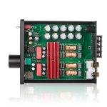
Ideas: Probably there is kind of a bandpass filter somewhere included on the board?! I've read an interesting article about it here. Can not identify it on the board yet. Attached some pictures of "real life situation" and "marketing material".
Do you have any tips for me?
Would appreciate any help from your side
Have a lot of capacitors and resistors around me for experiments.
THANK YOU!
I'm struggeling with getting low frequency output out of my (cheap) TPA3116D2 amp for weeks now. Time to post this message and ask the experts for help.
Field of use: Using the AMP for LFE (bass shaker aka "Buttkicker" for tactile feedback in race and flight sims) especially between 20-80 Hz
Amplifier: Nobsound TPA3116D2 2.0 Stereo AMP, used with 19V 5A power adapter
Speaker/LFE: SINUS LIVE BASS PUMP III 4 OHM
My expertise: Basic knowledge in electronics (can distinguish between capacitors, resistors, transistors
). Soldering is fine. Able to exchange single components in electronic devices. Basic understanding of how an AMP is working.Original situation: Bass Shaker was almost not working at all and AMP had really high gain. Volume knob was adjustable just about a 1/10 of an inch between "no sound" and "too loud".
What I've already done/Current situation: I've read through several articles and have figured out, that the AMP had an 36 db gain by default. Removed 2x 100kOhm resistors (2x because of Stereo) and exchanged 2x 47kOhm resistors by 2x 5k6Ohm resistors according to the datasheet. Gain is perfect now. Also changed the WIMA input capacitors from 2x 0.1microF (why the hell did they put 0.1microF on the board?) to 2x 1.5microF WIMA foil capacitors (WIMA MKS 4 1.5microF 100V 10%). Low frequency throughput is better, but still cut off or at least dramatically reduced below about 35 Hz. According to spec sheet I should have a gain of 20 db and a high pass filter cut of at 1.8 Hz.
Interesting fact: the lower the frequency the more it sounds like a piston slap sound coming from the bass shaker.
Desired situation: Low frequency output down to 20 Hz to use the full width of the LFE and the software tools for simulators I want to use.
Ideas: Probably there is kind of a bandpass filter somewhere included on the board?! I've read an interesting article about it here. Can not identify it on the board yet. Attached some pictures of "real life situation" and "marketing material".
Do you have any tips for me?
Would appreciate any help from your side
Have a lot of capacitors and resistors around me for experiments.
THANK YOU!
Attachments
Hi together - amazing community here - thumbs up!
I'm struggeling with getting low frequency output out of my (cheap) TPA3116D2 amp for weeks now. Time to post this message and ask the experts for help.
Field of use: Using the AMP for LFE (bass shaker aka "Buttkicker" for tactile feedback in race and flight sims) especially between 20-80 Hz
Amplifier: Nobsound TPA3116D2 2.0 Stereo AMP, used with 19V 5A power adapter
Speaker/LFE: SINUS LIVE BASS PUMP III 4 OHM
My expertise: Basic knowledge in electronics (can distinguish between capacitors, resistors, transistors
Original situation: Bass Shaker was almost not working at all and AMP had really high gain. Volume knob was adjustable just about a 1/10 of an inch between "no sound" and "too loud".
What I've already done/Current situation: I've read through several articles and have figured out, that the AMP had an 36 db gain by default. Removed 2x 100kOhm resistors (2x because of Stereo) and exchanged 2x 47kOhm resistors by 2x 5k6Ohm resistors according to the datasheet. Gain is perfect now. Also changed the WIMA input capacitors from 2x 0.1microF (why the hell did they put 0.1microF on the board?) to 2x 1.5microF WIMA foil capacitors (WIMA MKS 4 1.5microF 100V 10%). Low frequency throughput is better, but still cut off or at least dramatically reduced below about 35 Hz. According to spec sheet I should have a gain of 20 db and a high pass filter cut of at 1.8 Hz.
Interesting fact: the lower the frequency the more it sounds like a piston slap sound coming from the bass shaker.
Desired situation: Low frequency output down to 20 Hz to use the full width of the LFE and the software tools for simulators I want to use.
Ideas: Probably there is kind of a bandpass filter somewhere included on the board?! I've read an interesting article about it here. Can not identify it on the board yet. Attached some pictures of "real life situation" and "marketing material".
Do you have any tips for me?
Would appreciate any help from your side
Have a lot of capacitors and resistors around me for experiments.
THANK YOU!
I see that the output filters are 680 nf.
In PBTL mode you should use 1uF. Many boards have this same issue. I am waiting for my 1uF caps to change in mine as well.
You could try changing those output caps for 1UFs and see if that improves something.
Hi,I spend some time to read many posts to gather all the mods ,how they influence sound, output filters , snubbers, values of electrolytic capacitors and more....
I will also remove those 1K resistors but maybe i replace them with something like 33K not sure though. I will also remove the 330p caps or maybe replace them with 100p.
Do you have your gain changed at 20dB or 36db?For me its 36dB I havent changed it yet and there is also some hiss when nothing connected.
I wish this module had decoupling smd caps very close to power supply pins of each tpa3116.it has but they are located further away.
The blue resistors on the output snubber have a value of 1ohm but datasheet states 3.3ohm. I havent found an answer for this so far.
I have received some boards from china that have the 1Ohm resistors as filters as well. What I noticed is that, those will actually make the inductors heat up quite a bunch.
I changed all mine for 3.3R and the inductors aren't heating up as before.
I personally use only 20DB as well. I've tried many situations to use 26DB but no matter how hard I tried, cabling and so on, nothing ever got rid of the hiss.
Since I use my amp as a desktop/pc AMP, I'd rather have less noise.
Hi.Can you post a photo of your board first?
A 12v (1A) psu is suited only for low level listening volumes.
What is the impedance of the speakers you drive?
Maybe you overdrive the amplifier hence distortion is normal or u need a more current capable psu.
If these 4 blue MKT have a value of 1uF,better change them to 2.2uF wima.they fit there nicely if your PCB is same as mine.
I had another listen today and I think that there is sufficient volume to satisfy my tastes at the moment.
Hi Maouna,
It was not easy to find the board but finally it was there.
I checked with my Ohm-meter and you are RIGHT, there is a 1K and a capacitor across the input! It should not be so and my first intuition is to remove the 1K and the capacitor (from each channel). Perhaps it was a layout mistake or perhaps they were added in desperation over hiss.
I use my TPA6120-based headphone amplifier for input and that one can pull almost anything so I didn't notice.
Well spotted! Unfortunately another board that needs modification. Is that why the board suddenly became so cheap?
I haven't got time to do the "modding" right now but I will report back when done.
I have removed the 1k resistors, but not the caps mentioned above. Do you know what happens if the caps across the input are removed?
I see that the output filters are 680 nf.
In PBTL mode you should use 1uF. Many boards have this same issue. I am waiting for my 1uF caps to change in mine as well.
You could try changing those output caps for 1UFs and see if that improves something.
Thanks for your reply and idea!
I've changed the 680 nF to 1.5uF caps (don't have 1.0uF foil caps right now, just elco caps). Unfortunately, no improvement
Changed it just for the right speaker output - no difference to before and no difference between left and right. Perhaps measurable but can not feel any difference.Thanks for your reply and idea!
I've changed the 680 nF to 1.5uF caps (don't have 1.0uF foil caps right now, just elco caps). Unfortunately, no improvement
Hm.. I don't have any 1uFs of that needed size to test properly on my end, but I thought that could improve output filters.
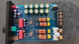
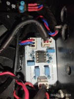
I am curious though, I see that your board has 2 big capacitors, but usually there's 2 input caps per side (4 in total). What value is those tiny blue caps on your board? Just after the wima ones you used.
Hi together - amazing community here - thumbs up!
I'm struggeling with getting low frequency output out of my (cheap) TPA3116D2 amp for weeks now. Time to post this message and ask the experts for help.
Field of use: Using the AMP for LFE (bass shaker aka "Buttkicker" for tactile feedback in race and flight sims) especially between 20-80 Hz
Amplifier: Nobsound TPA3116D2 2.0 Stereo AMP, used with 19V 5A power adapter
Speaker/LFE: SINUS LIVE BASS PUMP III 4 OHM
My expertise: Basic knowledge in electronics (can distinguish between capacitors, resistors, transistors
Original situation: Bass Shaker was almost not working at all and AMP had really high gain. Volume knob was adjustable just about a 1/10 of an inch between "no sound" and "too loud".
What I've already done/Current situation: I've read through several articles and have figured out, that the AMP had an 36 db gain by default. Removed 2x 100kOhm resistors (2x because of Stereo) and exchanged 2x 47kOhm resistors by 2x 5k6Ohm resistors according to the datasheet. Gain is perfect now. Also changed the WIMA input capacitors from 2x 0.1microF (why the hell did they put 0.1microF on the board?) to 2x 1.5microF WIMA foil capacitors (WIMA MKS 4 1.5microF 100V 10%). Low frequency throughput is better, but still cut off or at least dramatically reduced below about 35 Hz. According to spec sheet I should have a gain of 20 db and a high pass filter cut of at 1.8 Hz.
Interesting fact: the lower the frequency the more it sounds like a piston slap sound coming from the bass shaker.
Desired situation: Low frequency output down to 20 Hz to use the full width of the LFE and the software tools for simulators I want to use.
Ideas: Probably there is kind of a bandpass filter somewhere included on the board?! I've read an interesting article about it here. Can not identify it on the board yet. Attached some pictures of "real life situation" and "marketing material".
Do you have any tips for me?
Would appreciate any help from your side
Have a lot of capacitors and resistors around me for experiments.
THANK YOU!
We have a different board. What is the purpose of the opamp in your board? maybe the problem of distortion and poor low frequency response lies somewhere there....can you design the circuit around the opamp? track the route of the input signal from the rca until it enters the opamp and goes out from the opamp to the input of the tpa3116
Last edited:
Hm.. I don't have any 1uFs of that needed size to test properly on my end, but I thought that could improve output filters.
I am curious though, I see that your board has 2 big capacitors, but usually there's 2 input caps per side (4 in total). What value is those tiny blue caps on your board? Just after the wima ones you used.
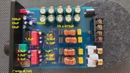
Appreciate your help! Please find the cap values attached
Interesting fact: all the 3.3uF caps are marked as 1.0uF on the board! Definitely it is saying 1.0uF on the board but there are 3.3uF caps installed. I have put a red rectangle around the caps that differ between board imprint and caps installed.
We have a different board. What is the purpose of the opamp in your board? maybe the problem of distortion and poor low frequency response lies somewhere there....can you design the circuit around the opamp? track the route of the input signal from the rca until it enters the opamp and goes out from the opamp to the input of the tpa3116
Thanks for your reply as well. Don't know exactely. Seems to be a similar question to the thread described here. There they write "Unfortunately, the F3 of the 1st order HP section is set at ~34Hz limiting low frequency. This is easily solved by replacing two 1uf electrolytic caps with a 4.7uf ones - same physical can size. That lowers the HP F3 to ~ 7hz." If I recognize the caps correctly it must be the 2x 3.3uF on the lower left.
Honestly, I'm not able to fullfill your recommendation and "track the route of the input signal". Don't have enough expertise to do so - and probably not enough measurement equipment
Attachments
Appreciate your help! Please find the cap values attached
Interesting fact: all the 3.3uF caps are marked as 1.0uF on the board! Definitely it is saying 1.0uF on the board but there are 3.3uF caps installed. I have put a red rectangle around the caps that differ between board imprint and caps installed.
Regarding the link you posted, that only plays a role if the amplifier gain is anywhere over 20DB. Since you're set at 20DB, the 1uF caps should be enough in the RC filter configuration, unless there's something we're missing.
At this point, I do believe your issue could be the OpAmp/PreAmp stage.
The capacitor values are ok/over the necessary ratings I would assume.
Once @FauxFrench told me it's not really great to use bigger input caps than needed, and it didn't take me long to figure that out, when trying some 10uF input at 20DB, I noticed a lot of distortion in lower frequencies.
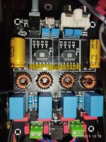
I finished my Desk amplifier, I will only change my PSU to a MeanWell one now as mine seems to consume too much idle power, some pics attached.
My board is the Aiyima one. The bad thing about it is not having a screw mount heatsink, but I got some plaster to put on it.
List of mods to the board:
- Input Caps changed from 1.5 uF to 1uF 63V Epcos
- Output filter cap changed from 680nF to 1uF 450V Epcos
- Bootstrap capacitors changed to higher quality Wurth Ceramics (220nf)
- DC caps changed to Nichicon FG 470uF/35V
- Pot changed to better quality A10K (from the B50K included)
Besides those, nothing else was changed. The white board in the picture is the a simple non-inverting amplifier with a OPA2132P I developed, nothing special about it. I made it tiny to fit in that space.
No hiss, no pop on/off, just as I wanted.
Cheers @FauxFrench for helping everyone a lot
Attachments

Appreciate your help! Please find the cap values attached
Interesting fact: all the 3.3uF caps are marked as 1.0uF on the board! Definitely it is saying 1.0uF on the board but there are 3.3uF caps installed. I have put a red rectangle around the caps that differ between board imprint and caps installed.
Thanks for your reply as well. Don't know exactely. Seems to be a similar question to the thread described here. There they write "Unfortunately, the F3 of the 1st order HP section is set at ~34Hz limiting low frequency. This is easily solved by replacing two 1uf electrolytic caps with a 4.7uf ones - same physical can size. That lowers the HP F3 to ~ 7hz." If I recognize the caps correctly it must be the 2x 3.3uF on the lower left.
Honestly, I'm not able to fullfill your recommendation and "track the route of the input signal". Don't have enough expertise to do so - and probably not enough measurement equipment
the circuit around the opamp propably has wrong R-C value components in its input /output or in its bias circuit since it works with single supply.Theres no need to have any measurement equipment.just follow the tracks from the down left input jack until it reaches the opamp and goes from the opamp to the input of the tpa3116 and draw the routes and components to a paper do it for one channel. in my case i used a torch to distinguish the tracks in my black pcb
you can unsolder these big red wimas if it helps you to see the tracks. Also it would be better to replace those 2 1/4w resistors with an smd type because if it ever happens to touch them with force by mistake,the pads will be destroyed
Last edited:
I did some modding to my XH-M590, reduced the gain and added some beefier PS caps, but found that at a certain sound level (reasonably high) I am getting some distortion. I have just removed the 1k resistors suggested a few posts back from here. The sound is very good until I get to a certain level and the distortion intrudes again. I have tried both 12v (1A) and a 24v supply (5A) and the results are the same,
The only thing I can thing of looking at now are the input caps, but am not sure which ones these are. There are 4 blue MKT type caps near the RCA sockets, but there are also some SMD caps in that area. Any ideas chaps?
UPDATE: I have finally solved the problem of distortion at higher levels. I had previously tried a more powerful PS as mentioned above with no improvement. I have now made a regulated stiff 24v PS. I had some Teddy Pardo Regulators lying around from years ago so I used these. So, the only thing left to ask is about the SMD caps near the input. I have removed the 1k resistors and wonder if there is any point in removing these caps?
UPDATE: I have finally solved the problem of distortion at higher levels. I had previously tried a more powerful PS as mentioned above with no improvement. I have now made a regulated stiff 24v PS. I had some Teddy Pardo Regulators lying around from years ago so I used these. So, the only thing left to ask is about the SMD caps near the input. I have removed the 1k resistors and wonder if there is any point in removing these caps?
I've been using 24v Industrial PSUs for a while, but man, my old one was bad and I didn't know how till now.
I just received my Meanwell PSU, seems like an original one as all components are well put together and seem original. The difference in sound quality, just from changing the PSU was noticeable. There is actually even less noise now, even with the pot turned all the way up, there was a small bit of hiss at maximum volume with the previous PSU.
I previously had one of those cheap-o chinese ones, two actually. One of them blown up out of nowhere and I think the transformer got toast.
Anyways, I just noticed while looking at my pictures I have those resistors/caps in the signal path. To be fair, I'd rather remove ceramics from the signal line as much as possible. The Bootstrap on my board would require those TDK MLCCs which I can't get right now.
Did you just remove them or shorted?
I just removed the 1k resistors.
Thank you Puffin, I removed them.
I did take out the ceramics as well. My board had 2k2 resistors and 100pF caps.
There is definitely more volume now
- Home
- Amplifiers
- Class D
- TPA3116D2 Amp