Thank you, FauxFrench, for your comprehensive answer and primer for a dim-witted pupil! ")
I will remove the board (+ heatsink) and check the path and components on the input paths to the IC per your description.
I will remove the board (+ heatsink) and check the path and components on the input paths to the IC per your description.
The dude abides.Please first take account of bucks bunny's very relevant observation and comment
Now it starts getting more complicated. When a class D amplifier starts up, an output bias circuit slowly raise the voltage of the two output lines to a level close to half of the supply voltage before each output line starts switching high-low-high-low etc. When the switching starts at around 400KHz you can no longer rely on the voltage shown on your multimeter. Would you have access to an oscilloscope (a simple one will do).
Unfortunately I do not have access to an oscilloscope. If, armed with my multimeter, I can find an obvious fault with a board component I should be capable of replacing it, but that's probably going to be about the extent of my diagnostic/repair ability.Would you have access to an oscilloscope (a simple one will do).
It is a $8 board. We can continue just to learn from what we find but it will be quite an effort from you to recover 8$.
With only a multimeter, your diagnostic capabilities are limited.
I still believe that a leaking input capacitor is a possibility. As I have a simple oscilloscope, I would check the output waveforms but that is not possible without an oscilloscope.
What you can do is to turn the volume potentiometer fully down, connect a speaker on each channels and turn the amplifier on. Then you measure the DC voltage from supply “-” and to each of the four output terminals (4 measurements). The values will not be precise due to the carrier signal (400KHz) but we should notice a difference between the left and the right channel.
Yes, agree completely! It is only an $8 board, and I really appreciate all the help - if there's an easy fix it will be a bonus, but if I can learn something from it, even better
I have not yet disassembled the board from its cabinet to visually inspect it, that may be this evening's project.
With speakers connected, volume at zero and no signal or media playing on the input, the figures are as follow (voltages are rounded up from nearest measured number, eg; 5.88V, as there was some fluctuation as noted):
*Edit - after another trial (powered off, powered on again), I am seeing different numbers:Supply "-" to Right "+": 6V
Supply "-" to Right "-": 9V
Supply "-" to Left "+": 10V
Supply "-" to Left "-": 6V
Supply "-" to Right "+": 6V
Supply "-" to Right "-": 5V
Supply "-" to Left "+": 4.2V
Supply "-" to Left "-": 6V
Last edited:
Many thanks for the measurements.
They demonstrate the problem of using a multi-meter on such a (rather) high frequency square-wave signal with a DC-offset. When there is no sound or reaction from a speaker, the potential on the two speaker terminals has to be the same. Nevertheless you measure a difference which is due to the measuring error of the multi-meter.
Much more interesting is that your measurements on the good right channel and on the “silent” left channel are about in the same range. This could indicate that the output carrier signal is present on both the right and left output. But, that the sound-signal is lost somewhere on the left channel.
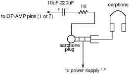
Do you have:
- an electrolytic capacitor in the range 10uF-220uF?
- a resistor close to 1KOhm?
- a wired ear-plug/ear-phone/headphone?
If so, you can make a simple “sound-finder” for checking where music is found and where not, in the circuit.
A sketch of the simple circuit is appended.
With that simple circuit you can hear in the ear-pieces if there is a music signal at the output of the OP-AMPs. The sound-level will not be high.
I have tried to draw the 3.5mm plug of a wired ear-plug/ear-phone/headphone. You use the outer-end terminal (not really round) and the one (ring-terminal) next to it, but not the GND terminal closest to the plastic cover. This way you have sound in both left and right ear-piece.
No speakers. Put power on the amplifier, volume full up, music from the source, Then you connect (without short-circuiting anything!) the free end of the capacitor to pin 1 and after that pin 7 of each OP-AMP while you listen if there is music in the ear-pieces.
They demonstrate the problem of using a multi-meter on such a (rather) high frequency square-wave signal with a DC-offset. When there is no sound or reaction from a speaker, the potential on the two speaker terminals has to be the same. Nevertheless you measure a difference which is due to the measuring error of the multi-meter.
Much more interesting is that your measurements on the good right channel and on the “silent” left channel are about in the same range. This could indicate that the output carrier signal is present on both the right and left output. But, that the sound-signal is lost somewhere on the left channel.
Do you have:
- an electrolytic capacitor in the range 10uF-220uF?
- a resistor close to 1KOhm?
- a wired ear-plug/ear-phone/headphone?
If so, you can make a simple “sound-finder” for checking where music is found and where not, in the circuit.
A sketch of the simple circuit is appended.
With that simple circuit you can hear in the ear-pieces if there is a music signal at the output of the OP-AMPs. The sound-level will not be high.
I have tried to draw the 3.5mm plug of a wired ear-plug/ear-phone/headphone. You use the outer-end terminal (not really round) and the one (ring-terminal) next to it, but not the GND terminal closest to the plastic cover. This way you have sound in both left and right ear-piece.
No speakers. Put power on the amplifier, volume full up, music from the source, Then you connect (without short-circuiting anything!) the free end of the capacitor to pin 1 and after that pin 7 of each OP-AMP while you listen if there is music in the ear-pieces.
Attachments
Last edited:
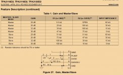
I know of two ways to get rid of the very annoying hiss: lower the input impedance and/or reduce the gain.
With a 5KOhm potentiometer, the input impedance is low enough.
The gain, you are already aware of, is changed with the resistor combination. R1=39K/R2=100K is a setting for 32dB gain. By removing R2 (100K) you get the minimum gain of 20dB. According to the datasheet, R1 should then be 5.6K. Replacing an SMD resistor is difficult while only removing one is doable.
I had 47K/75K for 36dB gain and by only removing the 75K I got 20dB gain. So, for a start leave the 39K (R1) in place, it will most likely work like that.
Lastly, the hiss could be caused if the TPA3116 input coupling capacitors are of a poor quality electrolytic type.
So, after ~3 years, I finally fixed the annoying buzz/hiss the front and surround output my Aliexpress 5.1 receiver (w/ x4 TPA3116) had.
It seems that the gain was indeed the issue.
For the FRONT gain I removed 100K resistor, then I tested to find out the output volume was low. So I decided to replace the 39K to 5K8 resistor.
Don't know if it's placebo or not, but after this change the buzzing/hissing is gone and volume is ok.
For the Surround gain, I only removed the 100K resistor.
Here are image of before/after:


@FauxFrench - thank you very much for the tip back then in 2018
Got this 2 for 1 sale on amazon US for $13.49. Some pics. I just got it and sounds great at half volume. Only one speaker(not really great sounding more of surround speaker, but clear enough) hooked up for listening and used my player with Flac files. Used a 12volt cable I had laying around and spliced it. It can take 24v, so it can go louder! Used a guitar knob I had and looks neat. I'll make a DIY case later.
Not sure if I am reading your post correctly, but 12v might be too low to obtain good sound from a TPA3116 amp. The distortion would come in too early. There are a few more comments about that board in this thread:
Help Identify This TPA3116 Board
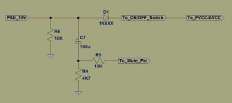
I've got a sure TPA3116D2 that I was trying to put the anti-pop circuit onto. I put a diode across the resistor as shown in the image. I held it there and plugged the amp in to see if it fixed the turn-on pop. Maybe not the brightest idea but I didn't know which resistor was going to the mute pin and this one seemed a likely candidate. Something definitely happened and now there is no sound. Speakers are dead quiet at full volume, the board LED still lights up as expected and fades on power off. There is 12v coming from the mute pin. I'm wondering if the short circuit protection latch is engaged and I need to "drive the SDZ pin low which clears the shortcircuit protection latch."
Anyone have any idea what I might have done to the board and if I can fix it?
Many thanks in advance for any help!

Anyone have any idea what I might have done to the board and if I can fix it?
Many thanks in advance for any help!
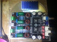
Hello.Today my Tpa3116 arrived.
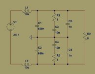
It has four 470uF/35V YXG series.
If i am right both chips are configured as master with a gain of 36db each.(R1=47K,R2=75K as in the datasheet,in my pcb R1 coresponds to R4,R10 and R2 to R3,R9).
There is a RC circuit connected to mute pin.
Output filter has the values shown below.
I will replace the electrolytics with low ESR ones but what value?
1000uf/35V or 470uF/35V?
Are the output filter values ok? Should i add snubber networks before the output coils?
I will also change the gain to 20 or 26 db and replace input caps.what gain do you suggest?
There are also two 1k resistors near the pot and they seem to provide 1k input impedance which is low but they where propably selected due to the high gain configuratio of 36db to avoid noise.
Attachments
Yes, both are configured as master.
I will replace the electrolytics with low ESR ones but what value?
1000uf/35V or 470uF/35V?
I would use 1000uF/35V if they are of the low ESR type. Some say that this higher value makes the sound more "shouty". I'm no expert on sound details.
Are the output filter values ok? Should i add snubber networks before the output coils?
Please look at Figure 37 of the datasheet: https://www.ti.com/lit/ds/symlink/tpa3116d2.pdf . Snubbers before the chokes are not mentioned by TI and I haven't tried. It is mainly a sound quality issue and not within my expertise.
I will also change the gain to 20 or 26 db and replace input caps.what gain do you suggest?
It depends fully on the output amplitude of your source. Less gain means less noise but requires more amplitude and less output impedance from the source. I use a TPA6120 based headphone amplifier as source so I have a high source amplitude and can use 20dB TPA3116 gain.
There are also two 1k resistors near the pot and they seem to provide 1k input impedance which is low but they where propably selected due to the high gain configuratio of 36db to avoid noise.
1K as input impedance seems very low. Are you sure that the 1K is not in series with the input?
Last edited:
I've tried over a dozen TPA3116 modules and the XH-M590 is certainly one of the better well behaved modules. Personally I can't see the point of modding it unless there's something you don't like in the sonics or have an issue.
All the rest went in the bin except for the blue/black Danzz module which works well.
All the rest went in the bin except for the blue/black Danzz module which works well.
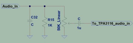
1K mounted like that across the input terminal is very unusual. If you measure with your Ohm-meter across an input terminal, do you measure 1K?
yes i also verified it with ohmmeter.It gives 974ohm which verifies the theoritical result of parallel combination of 50K and 1K.
Tracks can be clearly seen but it was easy to verify the input circuit. one side of the 1k resistor and C capacitor go to ground through a via while the othe sides are connected together with the input and the pot just like the schematic i posted.
Hi Maouna,
It was not easy to find the board but finally it was there.
I checked with my Ohm-meter and you are RIGHT, there is a 1K and a capacitor across the input! It should not be so and my first intuition is to remove the 1K and the capacitor (from each channel). Perhaps it was a layout mistake or perhaps they were added in desperation over hiss.
I use my TPA6120-based headphone amplifier for input and that one can pull almost anything so I didn't notice.
Well spotted! Unfortunately another board that needs modification. Is that why the board suddenly became so cheap?
I haven't got time to do the "modding" right now but I will report back when done.
Hi Maouna,
I removed both the 1K resistors and the capacitors. I had to remove the blue connector to get access. Anyway, I only use the RCA-connectors. The capacitors were 330pF.
The capacitors could cut off the high treble in case of a very high output impedance of the source. The 1K will reduce the input level for many sources without any advantage.
After removal I still had no hiss or other noise. At least the 1K resistors should be removed.
- Home
- Amplifiers
- Class D
- TPA3116D2 Amp