you have devise some means to limit primary current so that
the core don't saturate under load...in case your traffo is like
the one you showed, then a variac can help you....
another way would be a triac circuit controlling primary current..

http://www.iascaled.com/docs/psu-400w/an308.pdf
Thanks
Yes with triac wil also do, then I have a more robuust current regulator who can go also low for car welding use. a variac is no option such big thing I need.
triac allow go from 10 to 140 ampere, very nice indeed, early welders have a thyristor for this, I have some very big thyristors who can be also used, like 60 amp..
Hi All
I did want to make a weld transformer who has to go to max 140 amp on a 220 v grid.
I have found some used trafo,s who has a big core, amp get regulated with primary windings and fixed secondary windings, make the trafo for the highest amperage 30 % and the lowest 100% of time before it get to hot.
I did not find the formulas to calculate this properly.
regards
kees
watts follow current squared.
square root of 1/30%? is 1.82.
If you want a welder for 30% duty cycle at 140 amps, it needs to be large enough to supply 76.6 amps continuously.
but under what temperature rise? most stick welding is only 100% duty cycle, if you count 1 hour of continuous welding.. i mean you're not trying assemble a bulldozer in 1 week are you?
i have an arc welder, with magnetic shunts for current control.
the core weighs 22 kilograms. the primary is 90 turns of 6 awg aluminum wire and weighs about 2 kilograms. the secondary had two coils, one of 6.5mm square aluminum, the other of 5.8mm square aluminum. both coils weighed a total of 1.7kg.
it had a rather high velocity fan, and advertised somewhere around 120 amps continuous duty cycle.
Hi Johansen
My welder is a Co2 welder, trafo is burned and so want make a new one.
I do think on this moment to go for a inverter, I have the E71/33/32 core, with 20 windings 8 strains of 0.8 mm wire, I did want do the secondairy with band copper, I can do 38 mm wide and 1 mm thick copper or use 8 strains of 1.2 mm copper wire I have seen a lot people who make this trafos, but skin effect do play here a role.
I did weld yesterday with a inverter, these things weld very nice and stable.
Do I use the square mm formula also for band copper? like 32 x 1 x 3 = 96 amps, then this is 100 procent. for 76.6 I need then a copper band on secondairy 32 x 0.8 x 3 = 76.8 amps. see I this right?
Core can hold 38 mm wide band with is x 1 x 3 = 114 amp. or 38 x 0.8 x 3 = 91 amps for a higher duty cycle.
No I do not weld continously I do old cars and need most of the time low amps, sometimes with chassis parts I need high current.
I have a nice schematic of a inverter found, some are complicated for tig but not need that.
regards
kees
the thermal time constant of a small ferrite core doesn't offer you much time for welding duty. i realize this is what most cheap inverter welders do, to save money on the expensive ferrite cores.
you might try running several smaller cores, or stacking several smaller cores to get a core that is on the order of 15mm by 45mm or 60mm, rather than one large core that is 22mm by 32
you might try running several smaller cores, or stacking several smaller cores to get a core that is on the order of 15mm by 45mm or 60mm, rather than one large core that is 22mm by 32
Can you post the dimenstions of the lamels of your trafo? I can try to make a normal trafo who has a triac/thyristor power arrangement what makes it possible to go from 0 to 140 amp.
The E71 core can put out a lot of power, it is the biggest I can get, I did indeed see a invetion where there a 5 stacked cores.
The E71 core can put out a lot of power, it is the biggest I can get, I did indeed see a invetion where there a 5 stacked cores.
Attachments
core 7 by 7 mm:
100 turns of .3mm
14 turns of 1mm
15 turns of .2mm
core three: two 20 by 28mm cores stacked, for a cross section of 20 by 52
18 turns of 5 times 1.2mm wire
6 turns of 65 times .6mm
that all sounds about right.
the output choke is two 16 by 25mm cores, or 16 by 45mm cores, with an air gap of 5mm. i can't make the turns out.
looks like the current transformer is 100:1 ratio, wound with .2mm wire. sounds about right as well.
core 7 by 7 mm:
100 turns of .3mm
14 turns of 1mm
15 turns of .2mm
core three: two 20 by 28mm cores stacked, for a cross section of 20 by 52
18 turns of 5 times 1.2mm wire
6 turns of 65 times .6mm
that all sounds about right.
the output choke is two 16 by 25mm cores, or 16 by 45mm cores, with an air gap of 5mm. i can't make the turns out.
looks like the current transformer is 100:1 ratio, wound with .2mm wire. sounds about right as well.
Thank you for your help.
I have only two E71/33/32 cores who are some bigger, it is 3C90 material and al is 10800 without a gap, here she talk about a gap of 0.1 mm if I did see right.
the current transformer is indeed 100 windings and one winding of thick copper because it is in series with primairy.
Output choke is most of the time the same windings as the secondairy, read that somewhere.
Can I not use copper band for the secondairy? I did see that also a lot, I do not now how it behave what concern it,s skin effect.
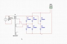
I have a rectifier who is for a three fase welder (380), I ask this because I maybe go wind a normal transformer for it, with single fase but two windings output, I did sim it and it looks like that works, however I am not sure.
I go make the inverter but first I try a normal trafo with a thyristor current regulator to get started fast, I need to weld a car before winter.
You now everything about it I do see, and thanks again for your interesting help.
It wil be a big job to get this windings on that core, the 65 x 0.6 is normally litze wire, so I have to twist them, the primairy is more easy 5 wires in one go next to each other, I did one and has not enough space.
regards
kees
Attachments
Last edited:
if you have a stack of dead TV's you can use the degauss coil for your litz wire.
also if you can get the cores from 6 TV flyback transformers that's probably sufficient, but you will have to increase the frequency to compensate.
The cores are no problem, I think a 1000 watt pc supply core and some stacket will help.
but both are some to small.
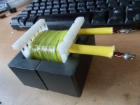
here I have this core and is 71/33/32 who alone is already sufficient. These has primary 8 x 0.8 wire but secondairy did not fit because the bobbin was 1.2 mm wider then core.
regards
Attachments
Last edited:
try and wind it without a bobbin? carve up a wood block to wind the coils on, then wrap them in mylar and slide the finished coil off the block onto the core.
Can you be more specific about the mylar? how to use, between the windings or make a bobine with it.
Is it better and safer to use two 71/33/32 cores? stacked because welder builder use one.
what thickness do i need.
Some say do not use inverter but trafo with a SCR system on secondairy, that works better then rimary SCR.
I go look at a trafo to see if it is heavy enough, but removel the laminates I think will be difficult.
thanks
kees
Last edited:
Hi
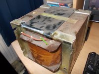
I have buy a old transformer for the build of that weld trafo, I put it tp 140 amp max with 22 volts, it has to be go dc so I use a rectifier and a big capacitor like I do see in the better welders, (why?).
dimension of the core middle leg is 10 x 6 cm, and the whole thing is 16.1 cm x 10.2 cm x 13.4 cm weighs 18 kilo.
This program I do use to get the windings however I do need 100 % duty cycle on max ampere, and I go make a secondairy SCR because this seems better.
Transformer Calculation v0.1
This is maybe a better site better calculator, more options like thinner wire and see how to use.
Calculating mains frequency power transformers
So I have for now a welder I can use and later I do the inverter.
Attachments
this polisch man has also a inverter, simple and a trafo who is secondairy wound with copper strip!! but is this not a problem with skin effect?.
he do use some smaller core then i have, maybe when I use two E71 20 wires 0.5 mm can be used in stead of 14.
Welding inverter up to 100A
regards
kees
he do use some smaller core then i have, maybe when I use two E71 20 wires 0.5 mm can be used in stead of 14.
Welding inverter up to 100A
regards
kees
the dimensions you gave for that 18 kilogram transformer don't check out right for a lossless cut.
can you give me the window area? (cross section available for the copper)
anyways, if its really that big, you should be able to wind something like 100 turns of 10 awg wire for a 240v 60hz primary, and 4x 10 awg wires in parallel for a 60 volt secondary.
you might split the secondary into two windings so you can have 8x 10 awg wires in parallel for a 30 volt winding.. or do a 40/80 volt winding.
as far as insulating a coil without a bobbin.. the biggest problem is avoiding scratching the wire. a single layer of something slippery like mylar or kapton is good to wrap around the coil after you've wound it.. also, sand the corners of the core down with a diamond file.
Last edited:
Hi Johansen
I do not mean 100% duty cycle on max but just 35% as the original trafo was for this welder on 145 ampere. this is a type error. machine can weld 100% on 85 ampere (lowest settings)
so I need ths amperes when calculate?
I think that even 120 ampere enough is for what I do, only bicycles and old cars, the SCR is for teh car metal very good, however I have the experience that rusted metal is
not welded wel, people say there is special weld wire for it.
coil bobine is 29 mm x 23 mm x 75 mm made of very strong material, however dismantle the trafo with the hars I think is not easy, some say put it hot and the dismantle is more easy.
You say your trafo has aluminium wire? I do indeed see this more often the last time, people here do not like that an prefere a copper winded coil.
regards
kees
Last edited:
I had to weld some 0.5mm to a panel that was just 0.3mm thick.
I turned my TIG down to 15A and did a lovely weld, by an amateurs' standard.
Big current is not always needed.
BTW, the fan inside the TIG unit is about 18" in diameter.
Aluminium is sometimes used to save weight particularly in portable transformers.
Aluminium can never give better performance.
I turned my TIG down to 15A and did a lovely weld, by an amateurs' standard.
Big current is not always needed.
BTW, the fan inside the TIG unit is about 18" in diameter.
Aluminium is sometimes used to save weight particularly in portable transformers.
Aluminium can never give better performance.
Last edited:
I had to weld some 0.5mm to a panel that was just 0.3mm thick.
I turned my TIG down to 15A and did a lovely weld, by an amateurs' standard.
Big current is not always needed.
BTW, the fan inside the TIG unit is about 18" in diameter.
Aluminium is sometimes used to save weight particularly in portable transformers.
Aluminium can never give better performance.
Andrew
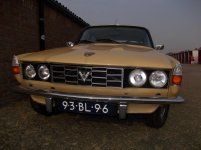
As you now I have to weld a rover P6 body, you now why, I did hear that titan wire can be used to weld on rust.
Attachments
- Home
- Amplifiers
- Power Supplies
- Tony's latest traffo DIY build