The P6 is mostly aluminium, if I remember correctly.
Stick welding will not be easy.
Ehhh no.
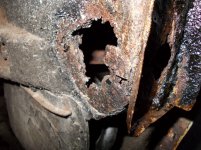
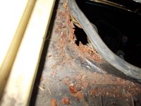
lot of iron, only boot door and bonnet is aluminium wich are fine..
the rest rust best..
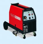
I do not stick welding, do not work, I have a cebora co2 welder with gas, that is where the trafo is for, I did buy the thing without trafo for cheap, so the rest was present and works, I am starter the dismanteling of trafo, heavy to do with al the hars, it is impregmented with that stuff, I keep the lowest 100% weld amperage as start, I think that is best, that is 85 amps.
Still I do not now about the square root 1/30% is 1.85 machine is 35 procent with 145 amps, max is 195 amps 20 procents.
The formula for the duty cycle is how you get 1.85 out of that, I am dutch so technical english is now as well.
thanks
regards
kees
Attachments
the formula is simply heat produced in the transformer is proportional to amps squared.
core losses are often negligible when it comes to welder duty, because the limit isn't the total amount of heat produced, but rather the limited thermal conduction from the center of the coils to the core.
some welders have air spaces through the coils and core to increase cooling, others don't.
for the epoxy impregnated transformers, aluminum is actually better because its thermal expansion coefficient matches the epoxy.
Here I am again
I have calc a transformer as test, I get it at 85 ampere 31 volts open connections.
But what happens if I go weld with it so without a regulator, go it then go to max ampere because of the short circuit what happens, and so have a suitable transformer.
Or.
Have I calc a transformer who is 140 ampere 31 volts open, but I think when go welding with this i get extreem high amps and trip the breaker.
Therefor I have calc 85 amps, what makes 140 or more 20 % weld current.
I see with trafos who has a switch and tapped primairy windings like in Co2 welders
that when on lowest setting somtimes as low as 10 ampere it has less dutycycle when set higher amps, this is only from primairy where the flux that way get very high when set on highest amp setting and so less primiry windings.
I have not this I use a regulator so current get lower from 85 amps open connections 31 to 15 volts.
Please let me now If I right, finding weld transformer calculators is not easy.
Have included a sheet calculation 85 ampere.
regards
Attachments
Last edited:
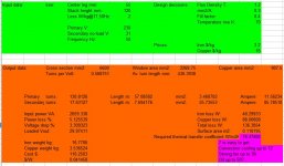
square root 1/30% is 1.85, this you tell me, and is 76 amps, I see on machine 100% is here 85 amps 18.2 volts, maybe it is a idea to use this seen the short cicuit action of the welder.
I have calc with this software also, see picture.
yehh just not there were i want.
regards
kees
I have calc with this software also, see picture.
yehh just not there were i want.
regards
kees
Attachments
is this diyAudio or diyWelding ?
welding is very usefull in diy audio like cases and such.
is this diyAudio or diyWelding ?
i wouldn't worry about this...let them have their fun....
")
welding is very usefull in diy audio like cases and such.
agreed, please carry on....
Thanks
But I am not yet where I want, how to calculate the weld trafo, unclear is a welding is short circuit and the most formulas do not take in account short circuit, so if I want a 120 amp welder 30% duty cycle what is enough, to start calculate the trafo windings for it because when I calculate a trafo 120 amps 25 volts, what happens when welding? I think breaker trips right away.
but make a trafo 76 amps 25 volts 100% duty cycle and do weld with that then I get 120 140 amps current because of short circuit action of welding.
So I need clearance here before I go wind coils.
regards
kees
Wel after some search, MIG welding needs a constant current source, a inverter is not usable and I do not now if there are constant current inverters, I do not think it so far so have to search.
therefore the MIG welders have trafos, for adjusting voltage and the wire speed adjust the current, more speed more voltage.
So with this I need to calculate a trafo.
regards
kees
therefore the MIG welders have trafos, for adjusting voltage and the wire speed adjust the current, more speed more voltage.
So with this I need to calculate a trafo.
regards
kees
Wel after some search, MIG welding needs a constant current source, a inverter is not usable and I do not now if there are constant current inverters, I do not think it so far so have to search.
therefore the MIG welders have trafos, for adjusting voltage and the wire speed adjust the current, more speed more voltage.
So with this I need to calculate a trafo.
regards
kees
Correction I need a constant voltage source for my intentions, the mig machine, so the transformer has to give that, this implements a coil in series with the transformer.
That is a big change, wich I have discover on time.
regards
kees
I think your earlier statement is correct.
The open circuit voltage of the welding transformers starts higher, usually around 40V to 80V.
As the arc strikes the voltage drops to around 10V to 20V.
It's effectively a constant current source.
The voltage across the arc depends on the gap one maintains and the current tries to stay constant.
The open circuit voltage of the welding transformers starts higher, usually around 40V to 80V.
As the arc strikes the voltage drops to around 10V to 20V.
It's effectively a constant current source.
The voltage across the arc depends on the gap one maintains and the current tries to stay constant.
I think your earlier statement is correct.
The open circuit voltage of the welding transformers starts higher, usually around 40V to 80V.
As the arc strikes the voltage drops to around 10V to 20V.
It's effectively a constant current source.
The voltage across the arc depends on the gap one maintains and the current tries to stay constant.
André
Not agree with this, read this paper.
Constant Current vs. Constant Voltage Output
Stick welding needs constant current source and MIG (wire feed) needs constant voltage (because of automatic feed of wire).
And so what to do with a inverter, have i build a normally power source with voltage feedback aca normal power supply and current protection.
The open voltage of my own MIG welder is 32 volts on max amps and has to be a voltage source the big coil in series with trafo act as the restistor to get this done.
regards
kees
watts follow current squared.
square root of 1/30%? is 1.82.
If you want a welder for 30% duty cycle at 140 amps, it needs to be large enough to supply 76.6 amps continuously.
but under what temperature rise? most stick welding is only 100% duty cycle, if you count 1 hour of continuous welding.. i mean you're not trying assemble a bulldozer in 1 week are you?
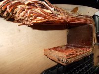
i have an arc welder, with magnetic shunts for current control.
the core weighs 22 kilograms. the primary is 90 turns of 6 awg aluminum wire and weighs about 2 kilograms. the secondary had two coils, one of 6.5mm square aluminum, the other of 5.8mm square aluminum. both coils weighed a total of 1.7kg.
it had a rather high velocity fan, and advertised somewhere around 120 amps continuous duty cycle.
Johanssen
Hi there
I have now the idea that I have find out how, it is the surace of the wire used, it do match with yours when 120 amps continu, for lower duty cycles the wire is just thinner and core sometimes smaller.
I have now seen that when I use the machine 100 % amperage and use this with the open max voltage I am where I need to be.
because my machine was a three fase with 170 amps (is close to 30% duty cycle when 85 amps) I can not use the 100% current for the new trafo and so I use your 76 amps for 30% on max voltage (32 volts), and I need a stabilization coil for after the diodes and big elco,s.
Bigger wire for 100 procent duty do also not fit, yours is a bit bigger with 22 kilos so that big enough.
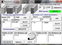
What I get from program is for 76 amps 32 volts.
primairy 168 windings 2.5 mm wire.
secondary 24 windings 6.1 mm wire for 32 volts, (I need some more for diode rectifier 1.2 volts but because of elco,s proberly not needed).
stabilization coil is 30 windindings 6.1 to 8 mm wire on core with airgap. (without you can not weld with it).
thanks for help.
kees
Last edited:
Thanks
But I am not yet where I want, how to calculate the weld trafo, unclear is a welding is short circuit and the most formulas do not take in account short circuit, so if I want a 120 amp welder 30% duty cycle what is enough, to start calculate the trafo windings for it because when I calculate a trafo 120 amps 25 volts, what happens when welding? I think breaker trips right away.
but make a trafo 76 amps 25 volts 100% duty cycle and do weld with that then I get 120 140 amps current because of short circuit action of welding.
So I need clearance here before I go wind coils.
regards
kees
another way would be several primary taps so that you can decrease secondary voltage to limit current....another way is to make the air gap adjustable mechanically...
big traffos have big thermal mass, and when using for welding where current draw is intermittent, then you can overload your traffo a few minutes without serious consequences.....
Yes this is right, amps per mm2 and how close I can wind al this give more power.
I want to use a SCR circuit to limit current, it seems this works oke when snubber is calculated properly.
But one thing is important it needs a constant voltage source, so a choke is very important.
I have a core 55 x 120 mm, this is not very big but for now I have nothing else.
regards
kees
the amount of copper you can squeeze in in your available winding window limits your capacity...
having a core capacity of say 2500va per your calculator does not automatically
translate that your copper can handle that amount of power...this the reality of space limitations...
having a core capacity of say 2500va per your calculator does not automatically
translate that your copper can handle that amount of power...this the reality of space limitations...
- Home
- Amplifiers
- Power Supplies
- Tony's latest traffo DIY build