Re: Re: Re: Re: Re: To Make Good PCB at home
Hi Fotios,
Yes, there are some similarities between us! I am now 50 (almost 51). I was fascinated by electronic equipment from a very young age and built my first Heathkit at around age 10. I built one of their small vacuum-tube oscilloscopes when I was 11 or 12. Unfortunately, I had no relatives who lived close to me who were interested in electronics, as you did. [So I am now jealous. ;-) ] (Much later, when it was basically too late, I found out that one of my uncles was a professor of engineering at a university!) So I didn't really understand much about what I was building until I got an EE degree, in 1978 (Purdue Univ.). However, then I sort-of specialized in 'automatic control theory', instead of circuits, although, of course, I still took many courses dealing with circuits, and transistor design, digital design, and much, much more (But EE, where I was at least, was mostly about the mathematics, it seems; systems theory (frequency and time domains), probabilistic/stochastic systems theory, communication systems theory, non-linear network theory, etc etc). I also completed 24 credit-hours of graduate-level courses in EE and mathematics. After graduating, I got a job as an engineer, at McDonnell Douglas, working on the F/A-18 fighter/attack aircraft program, and helped solve a problem with structural vibrations feeding back through the flight-control system's sensors etc. I then worked on an automatic weapon-delivery system for the F-15 aircraft, which I can't tell you about, but which was really-really cooool! I made a *major* breakthrough, for that project, after which even just the name of the project was classified as Secret. (See. Not always too modest. ;-) After that, I quit my job and started a software company, which went extremely well for about 15 years, until my wife was diagnosed with cancer. We were told almost immediately that she would die within about one year. I decided that I could always start another company, or get another job, but would never have HER back again. So I let the software company crash and burn, so I could spend all of my time with her, and, later, take care of her. I have never regretted that decision. Around that time, I also started playing-around with actual circuits, again. Later, for a few years I bought, refurbished, and resold truckloads of things like oscilloscopes, spectrum analyzers, signal generators, etc; all military surplus. (Imagine a child with his own candy shop.") For the last few years or more, I have been trying to design and manufacture my own test equipment, and some other types of electronic stuff, and have been dabbling in audio. And WOW have I learned a lot more (and still am)! Anyway, my youngest child is now 17, and will be out of high school (i.e. grades 9-12), very soon. So I am now thinking about getting 'a real job', as an electrical engineer, again! I do still miss having other engineers to 'talk shop with', and to work with. I thought that that feeling would go away. But it never did, even after all these years. Also, in the back of my mind, I have always thought that I still had 'something else great' that I needed to contribute, somewhere. So I intend to find out.
For the last few years or more, I have been trying to design and manufacture my own test equipment, and some other types of electronic stuff, and have been dabbling in audio. And WOW have I learned a lot more (and still am)! Anyway, my youngest child is now 17, and will be out of high school (i.e. grades 9-12), very soon. So I am now thinking about getting 'a real job', as an electrical engineer, again! I do still miss having other engineers to 'talk shop with', and to work with. I thought that that feeling would go away. But it never did, even after all these years. Also, in the back of my mind, I have always thought that I still had 'something else great' that I needed to contribute, somewhere. So I intend to find out.
I am SO very sorry to hear that your father died of cancer at such a young age! You and my three children have something in common, then. Their mother died of cancer at age 44, when I was 41 and they were 8, 11, and 12. Such things are 'difficult beyond words'... (The best thing I can think of, to say to people who have recently lost a loved one, is to remind them to try to always remember that their loved one would want them to try to be happy and to try to thrive [because that's about the only thing that 'saved' ME].) Now, almost ten years later... here I am. My new motto: "Life is too short!".
Regarding making two-sided PCBs:
I usually transfer both sides at once. I line up the patterns with a bright lamp (a 'light table', or X-ray viewer, would probably be *very* helpful), tape them together on two sides (with the other two sides cut precisely on the board-outline lines, including one corner), put the board between them, and iron both sides, one after the other.
That part seems to work pretty well. And there are other refinements that can be used, for the alignment procedures.
But the main problem I have had with two-sided boards occurs only when I try to make a LONG board, such as one 9.75-inch-long board that I use in my Curve Tracer product. In that case, the laser printing is not 'linear'. i.e. the printing is stretched in some places and shrunk in other places, in the direction of the paper's motion through the printer. Sometimes, I can partially fix the problem, by making sure that the patterns go through the printer in the same direction. But it is not usually successful-enough, i.e. too-low % yield, and forced me to start using a professional pcb-manufacturing company, for those production boards. (I did also try running the paper through the printer several times, first, to heat it, hoping to "pre-deform" it, before printing the patterns. But that didn't help.)
I did recently upgrade my PCB software, which was previously limited to 1000 pads. That limit was why I could not print both sides of the 9.75" x 3" board on the same sheet, at the same time, which probably would have made the deformation at least equal for both patterns, which would have then at least allowed the holes to line up, for the two sides. But I have not tried it again, since I upgraded the software, because I now have a stockpile of professionally-made boards, for that one.
Of course, for production quantities especially, the professionally made boards are wonderful. Even just having plated-through holes, alone, makes them worth the cost, for me. I could also greatly-simplify my PCB layouts, if I would assume that all holes would be plated-through. Assembly is also greatly simplified, since I can now solder on only one side of the board. (This board has, literally, almost exactly 1000 solder pads, and is quite crowded with components, in some places. So it really was a pain to build it, without plated-through holes.)
I'm sorry that I blathered-on, for so long, about all of that.
fotios said:
Hi Tom
You are very modest, really! I am 49 years old and I am occupied with electronics from my 10s. This means from 1970 in my uncle lab who was repaired tube radios and TVs. I remembered the admiration of all for the first solid state radios (they called transistors and not portable radios at that time in Greece; what wonderful days in that time, unforgettable days). So, for 39 years I am an experimenter with all about electronics and electrics. I am graduate of the Greek public higher schools of electrician and electronic engineers (8 years of educational in these schools after the total 12 years of the first and secondary degree education, thus total 20 years in school while I worked simultaneously because my father was died from cancer in 1970 in his 39s when I was only 11 and he leaved to our family only a house and a little death pension. I write them so you can understand that our thoughts, our practical our skill and our views converge. So, many times only the reference of someone for something it is enough for me to I get the opportunity for a practical test. I don’t need the many explanations and instructions; because as you understand for so many years I have heard already something about all and I have enough experience about chemicals and procedures (I hope to not hear us the FBI because we are scientists and not terrorists!). Just today I tried your method and I found that the baked toner removed easy with nitric solvent (that which sell the paint stores) but I don’t know if it causes corrosion in the copper; instead for aluminum it is the most drastic cleaner without any danger for corrosion in it. BTW a drastic corrosive for cleaning aluminum surfaces from little scratches (which also remove totally the anodizing if we want) it is a solution of enough caustic soda (NaOH) with light warmed water.
As for the glossy papers, I got by chance from the local store of Cartridge World (it is international www.cartridgeworld.com) 4 different in weight glossy papers free for test (140GSM-185GSM-210GSM-270GSM) and I tried the 210GSM with success from first. Tomorrow I will try some transfers in PCBs so for etching copper (I use as you the same etchant solution of thinned HCL acid with little Hydrogen Peroxide) as for a silkscreen on the PCB. I will post the results. As for the paper removing from the sticking toner on copper it is most easy if we leave the PCB to soak in warm water for 20 minutes at least; so the last remaining layer of paper which is the most difficult to removed it is done easiest with little rub from our finger.
For double sided boards, after the printing we iron the one side transfer paper on the board and after removing the paper we drill some pad holes (6 to 8 are enough) near the corners and the middle of PCB with 0,7mm drill bit. On the other side paper we drill exactly the same pad holes corresponding to the first side drilled holes, before we iron the paper. From the sticking and cleaned side pattern, we pass thru the drilled holes some sewing pins as guides and we put the other paper with the aid of pins exactly in the right place. We stick the paper in the corners with tape so don’t can moved and we remove the pins. Now we are ready for the ironing process.
<snipped (sorry) to stay within 10000-character message limit>
Fotios
Hi Fotios,
Yes, there are some similarities between us! I am now 50 (almost 51). I was fascinated by electronic equipment from a very young age and built my first Heathkit at around age 10. I built one of their small vacuum-tube oscilloscopes when I was 11 or 12. Unfortunately, I had no relatives who lived close to me who were interested in electronics, as you did. [So I am now jealous. ;-) ] (Much later, when it was basically too late, I found out that one of my uncles was a professor of engineering at a university!) So I didn't really understand much about what I was building until I got an EE degree, in 1978 (Purdue Univ.). However, then I sort-of specialized in 'automatic control theory', instead of circuits, although, of course, I still took many courses dealing with circuits, and transistor design, digital design, and much, much more (But EE, where I was at least, was mostly about the mathematics, it seems; systems theory (frequency and time domains), probabilistic/stochastic systems theory, communication systems theory, non-linear network theory, etc etc). I also completed 24 credit-hours of graduate-level courses in EE and mathematics. After graduating, I got a job as an engineer, at McDonnell Douglas, working on the F/A-18 fighter/attack aircraft program, and helped solve a problem with structural vibrations feeding back through the flight-control system's sensors etc. I then worked on an automatic weapon-delivery system for the F-15 aircraft, which I can't tell you about, but which was really-really cooool! I made a *major* breakthrough, for that project, after which even just the name of the project was classified as Secret. (See. Not always too modest. ;-) After that, I quit my job and started a software company, which went extremely well for about 15 years, until my wife was diagnosed with cancer. We were told almost immediately that she would die within about one year. I decided that I could always start another company, or get another job, but would never have HER back again. So I let the software company crash and burn, so I could spend all of my time with her, and, later, take care of her. I have never regretted that decision. Around that time, I also started playing-around with actual circuits, again. Later, for a few years I bought, refurbished, and resold truckloads of things like oscilloscopes, spectrum analyzers, signal generators, etc; all military surplus. (Imagine a child with his own candy shop.
For the last few years or more, I have been trying to design and manufacture my own test equipment, and some other types of electronic stuff, and have been dabbling in audio. And WOW have I learned a lot more (and still am)! Anyway, my youngest child is now 17, and will be out of high school (i.e. grades 9-12), very soon. So I am now thinking about getting 'a real job', as an electrical engineer, again! I do still miss having other engineers to 'talk shop with', and to work with. I thought that that feeling would go away. But it never did, even after all these years. Also, in the back of my mind, I have always thought that I still had 'something else great' that I needed to contribute, somewhere. So I intend to find out.I am SO very sorry to hear that your father died of cancer at such a young age! You and my three children have something in common, then. Their mother died of cancer at age 44, when I was 41 and they were 8, 11, and 12. Such things are 'difficult beyond words'... (The best thing I can think of, to say to people who have recently lost a loved one, is to remind them to try to always remember that their loved one would want them to try to be happy and to try to thrive [because that's about the only thing that 'saved' ME].) Now, almost ten years later... here I am. My new motto: "Life is too short!".
Regarding making two-sided PCBs:
I usually transfer both sides at once. I line up the patterns with a bright lamp (a 'light table', or X-ray viewer, would probably be *very* helpful), tape them together on two sides (with the other two sides cut precisely on the board-outline lines, including one corner), put the board between them, and iron both sides, one after the other.
That part seems to work pretty well. And there are other refinements that can be used, for the alignment procedures.
But the main problem I have had with two-sided boards occurs only when I try to make a LONG board, such as one 9.75-inch-long board that I use in my Curve Tracer product. In that case, the laser printing is not 'linear'. i.e. the printing is stretched in some places and shrunk in other places, in the direction of the paper's motion through the printer. Sometimes, I can partially fix the problem, by making sure that the patterns go through the printer in the same direction. But it is not usually successful-enough, i.e. too-low % yield, and forced me to start using a professional pcb-manufacturing company, for those production boards. (I did also try running the paper through the printer several times, first, to heat it, hoping to "pre-deform" it, before printing the patterns. But that didn't help.)
I did recently upgrade my PCB software, which was previously limited to 1000 pads. That limit was why I could not print both sides of the 9.75" x 3" board on the same sheet, at the same time, which probably would have made the deformation at least equal for both patterns, which would have then at least allowed the holes to line up, for the two sides. But I have not tried it again, since I upgraded the software, because I now have a stockpile of professionally-made boards, for that one.
Of course, for production quantities especially, the professionally made boards are wonderful. Even just having plated-through holes, alone, makes them worth the cost, for me. I could also greatly-simplify my PCB layouts, if I would assume that all holes would be plated-through. Assembly is also greatly simplified, since I can now solder on only one side of the board. (This board has, literally, almost exactly 1000 solder pads, and is quite crowded with components, in some places. So it really was a pain to build it, without plated-through holes.)
I'm sorry that I blathered-on, for so long, about all of that.
Agus Widarto said:Waooow thank you mr fotios,mr gootee and all of you diy'er! i love's yuo!I Loves diy audio com , i loves internet!
God Bless You All...
regards
agus
Hi Agus
I am very happy that i helped you. Also may you know that these works needs patience. An experiment to make a large PCB (A4 size) with the baked toner laser printing way, showed me that it declines some from the original dimensions. Especially if in the board included ICs with many pins. For so big size it is better the way of presensetized pcb and the photoetchant because it is absolute precise in distances and dimensions in any size. For small pcb such as the standard Eurocard size of 100X160mm the method of toner it gives very good results.
Because we speak in all of your thread only about technics of making pcbs, we forgot to say some other significant things during the design, such as you may mitter the corners in tracks or yet better to round theme because the negative ions (electrons) have the bad habitt to concentrated in the peaks of corners in the tracks and produce thus unwanted capacitive loads. I quote bellow the photos of a double sided pcb which made in my mini lab for a power amplifier of 150W/8Ohms per channel. Look carefully the shape of tracks.
An externally hosted image should be here but it was not working when we last tested it.
Component side
An externally hosted image should be here but it was not working when we last tested it.
Solder side
An externally hosted image should be here but it was not working when we last tested it.
The pcb assembled
I wish you success
Fotios
sandstorm33 said:
But then come the FUN!!!..Drilling the result. I have trouble keeping the small carbide drill bits from breaking .....Anybody got a system for successful drilling???

Hey, sandstorm33
I have find the problem and resolved this in my Dremel drill press stand to not "plays" during its vertical motion. The problem it is the spiral spring which was slack and can be resolved by tighteening the spring by one tooth more in the cogwheel included in the littlte box on the right (you can open it by loosening only one screw) of the press drill stand. I am verry happy now, because after this i can use without fear my turbo shank carbide drills yet from 7mm. The only accident can caused from careless moovements of the PCB or the hand. With little attention and without hurry the work can be done without broken drills.
Fotios
Eva said:I find that positive presensitized PCB and inkjet transparencies are the easiest method. However, the four steps of the process should be done with great care because once something has gone wrong in one step you will have serious trouble to get the following steps right. On the other hand, good transparencies give a better error margin for UV exposure time. Optimum UV exposure time gives a good error margin for NaOH concentration in developer solution. Optimum developing results in almost fool-proof etching...
Hi Eva
What is the brand of the printer that you use? Also the brand of transparencies?
I report this because untill now i use my old Epson SC660 with the original transparencies of Epson also. I thing that the head of my printer (after 8 years of use) have clogged and i have little problems during printing the transparencies (little hole spots etc). Unfortunatelly, the new inkjets of Epson they don't print transparencies! I have searched thoroughly and the only brand that offers printing of transparencies (of A4 size) it is Cannon. Also Cannon offers its own transparencies. I have not tried ever the Cannon solution. Have you any idea or a suggestion about?
Fotios
A PCB maden at home
This PCB it is 380 X 270mm (two pieces of 190 X 270mm in reality joined between them with gold plated pins). It is double sided and used wire jumpers to pass the tracks from the component side to the solder side. The PCBs are presensitized type (blue adheshive! it needs about 10 to 12 min of UV exposure for good developement) and the films used are ready printed Epson transparencies from my old Epson SC660 inkjet. You can see with your eyes the result. The beatiful green protective lacker it is Peters solderable.
Fotios
An externally hosted image should be here but it was not working when we last tested it.
one thing i discovered that extends bit life and keeps the dust down...... water. when drilling, i keep a bit of water on the place where i'm drilling. first, it limits the bit temp and the work temp to 212F (100C), and it keeps the dust in a small blob instead of the air. it also is quite useful when drilling aluminum with a dremel tool. if the temperature goes unchecked, the aluminum under the bit liquefies, and it's difficult to drill. a drop of water limits the temp, and the bit chews right on through like it should. a lot of people use oil, but it heats to a higher temp, and leaves an oily (duh!!!) residue that must be cleaned off. water leaves no residue.
Hi Fotios, Just been looking at your pics over on other topic, fabulous job with the PCB,s. Like you I have an Epson inkjet and have been experimenting with "Diptrace" PCB package. I am using transparencies made for Epson inkjets by a company called "Jetstar" and have after a bit of experimentation been able to come up with excellent results. I have found it best to set up the printer properties for "matt paper" to put the most ink down, and to print in the highest photo (slowest) mode with contrast at max and brightness turned down. I was amazed just how fine I could produce PCB tracks, there was no fretting of the copper and no pinholes. Looking forward to the next installment of your pictures, it really is a first class job.
Why can't manufacturers all make boards like this instead of all glue and sellotape as we used to say.
Regards Karl
Why can't manufacturers all make boards like this instead of all glue and sellotape as we used to say.
Regards Karl

Fotios, just reading your earlier post about wanting a new printer. My Epson is model DX4050 and as I say, it's brilliant with the transparencies, I can go as fine as any commercial PCB in a manufacturers product (I mean surface mount here as well). I was amazed myself, but you do have to set printer properties as I mentioned to get perfect results.
Regards Karl
Regards Karl
unclejed613 said:one thing i discovered that extends bit life and keeps the dust down...... water. when drilling, i keep a bit of water on the place where i'm drilling. first, it limits the bit temp and the work temp to 212F (100C), and it keeps the dust in a small blob instead of the air. it also is quite useful when drilling aluminum with a dremel tool. if the temperature goes unchecked, the aluminum under the bit liquefies, and it's difficult to drill. a drop of water limits the temp, and the bit chews right on through like it should. a lot of people use oil, but it heats to a higher temp, and leaves an oily (duh!!!) residue that must be cleaned off. water leaves no residue.
Hi unclejed
Please accept my respects, because you are a big craftsman as it appears in so many threads where we met. How are you? I wish you the better.
Yes, the use of water it helps realy during drilling the hard epoxy copper clad boards, because these are very durable compared with veroboards which are made from bakelite. This is usefull especially for the HSS drill bits. As for the dust, indeed it is a disgusting thing. I use a small brush to wet from time to time the PCB during drilling with a solution of water with little liquid detergent for dishes (such as TRYL, AVA, i don't know the brands be on sale in US; anyone liquid shoap for hand washing dishes it is suitable). For drilling aluminum i prefer the use of diesel and enough patience to not melt (as you point out very corectly) the piece under proccess arround the cutting edge. With the use of diesel and slow proccess, you can drill a perfect circural hole yet with the use of a 14mm HSS drill bit instead of a hole cutter. For success, of course the piece under working must be tightened well in the drill press stand vice to stay absolutelly unmoving during the drilling.
Have you try these new Turbo Shank Carbide microdrills? As i refer in the previous post, these are amazing effective for hard epoxy PCB drilling and also very delicate to break under careless moovings of the piece under proccess or finger touches etc. Also can be used only with a precise vertical drill press stand such as Dremel. The moto tool must be absolutelly stable (without any horizontal wobble) during the vertical mooving. Also we must be absolutelly focused in our work to avoid any break from absence of mind which is the most common reason for breaking bits!
I order these bits from an UK e-bay online store named "Gloster Tooling" for 15Euros per pack of ten bits. The shipping cost offered from this store it is very little in comparison with other shops. Also, in the same store you can find anything from other cutting tools such as any type of milling cutters, nice center hole drill bits, drill bits of any alloy for any metal work, etc.
Fotios
Mooly said:Hi Fotios, Just been looking at your pics over on other topic, fabulous job with the PCB,s. Like you I have an Epson inkjet and have been experimenting with "Diptrace" PCB package. I am using transparencies made for Epson inkjets by a company called "Jetstar" and have after a bit of experimentation been able to come up with excellent results. I have found it best to set up the printer properties for "matt paper" to put the most ink down, and to print in the highest photo (slowest) mode with contrast at max and brightness turned down. I was amazed just how fine I could produce PCB tracks, there was no fretting of the copper and no pinholes. Looking forward to the next installment of your pictures, it really is a first class job.
Why can't manufacturers all make boards like this instead of all glue and sellotape as we used to say.
Regards Karl
Mooly said:Fotios, just reading your earlier post about wanting a new printer. My Epson is model DX4050 and as I say, it's brilliant with the transparencies, I can go as fine as any commercial PCB in a manufacturers product (I mean surface mount here as well). I was amazed myself, but you do have to set printer properties as I mentioned to get perfect results.
Regards Karl
Hi Karl
Thanks for your kind words and for the informations about the "stuff" you are using for PCB proccess. Please give me few minutes to check out the availability of all these you refer on the web and after i will reply to you.
Fotios
i've noticed that older dremel tools (probably from years of abuse) have a lot of lateral play in their bearings, and really are almost useless for pc board work. if i begin making boards, i think i will invest in a new dremel and use it only for pc boards. another feature i will look for is variable speed, or i'll just use a 600W dimmer. the cheap way out is to put a switch in series with the drill and put a 400V/6A diode across the switch terminals. when the switch is open, you get 1/2 line voltage at the drill. it's a device that's also useful for idling a soldering iron.
Mooly said:Hi Fotios, Just been looking at your pics over on other topic, fabulous job with the PCB,s. Like you I have an Epson inkjet and have been experimenting with "Diptrace" PCB package. I am using transparencies made for Epson inkjets by a company called "Jetstar" and have after a bit of experimentation been able to come up with excellent results. I have found it best to set up the printer properties for "matt paper" to put the most ink down, and to print in the highest photo (slowest) mode with contrast at max and brightness turned down. I was amazed just how fine I could produce PCB tracks, there was no fretting of the copper and no pinholes. Looking forward to the next installment of your pictures, it really is a first class job.
Why can't manufacturers all make boards like this instead of all glue and sellotape as we used to say.
Regards Karl
Hi again Karl
I checked the stuff you are using.
For the PCB drawing i use the EDWinXP 1.50 of Visionics which is a complette suite including also different simulators. It is cheapest from "Diptrace" and a downloadable upgrade of the Proffesional Non Commercial version it costs only 125 USD. Also in this price included two licences for two PCs if you ask them. I have paid as i remembered in 1999 the early version EDWin 1.6 N.C. Proffesional for todays 528Euros! but for buy the package including one demo CD and six activation Floppy Disks. Today the things are absolutelly different. I have also a
 full version of the "superb" Altium 6 Design Center (previous Protel), but as you i am familiar with the use of EDWin for 9 years. You know the rests; who is in position to spend his precious time to learn a different software be it so it is offered as a gift?
 Moreover all are about the same s--t
. A tanker of promises for amazing operations from the side of supplier of software, and finally two tankers of broken nerves from the side of the end user. 

For the printing now; i use for 8 years the SC660 with the transparencies of Epson and as you i make the same trick by setting the paper as Photo quality inkjet paper instead transparency for the same reason of putting the most amount of ink on the film. The Epson transparencies are excellent in absorption of ink and dry instantly. I taked a look on the JetStar that you reffer and indeed seems like most proffessional from Epson. The price it is almost the same between Epson and JetStar. For the printer, to be sincere, i had not searched in the class of multifunction printers. I bought as a stupid before 4 months the last model of Epson inkjet Stylus D120 for 110Euros
. For my unpleasant surprise i discovered that, when i had placed the first transparency for printing, the printer ejected the film and gave a message "there is no papper loaded"; naturally, because all the new printers of Epson are equiped with a stupid IR sensor to check the papper state!Now according to your report i seen that the DX4050 makes the job! Fortunatelly you prevent me from the buy of a new head (60Euros!) for the SC660. Thanks a lot. From tomorrow i will see for this DX4050.
I will back!
Fotios
Hi Fotios, I did not know the Epson's use IR sensor (never thought about it really), maybe that is why the Jetstar is recommended specifically for them, it does have a slight matt appearance. I have not tried other types of transparancies, perhaps these would be rejected as you have found. Now I don't no whether this is something you have experience of ! Inks. The Epson uses there own "Durabrite" ink which I believe is a pigment type ink and not a dye. I have only used these for PCB's and not the cheap "compatibles". Do you use original cartridges for your PCB work. In the U.K. Epson themselves have some very good deals on printers, I am sure they have similar site in your part of the world.
Regards Karl
Regards Karl
Mooly said:Some good general info here http://www.megauk.com
Hi Karl
Thanks for this nice link. Amazing stuff!!
For the printer, i have also a Cannon Pixma IP2000 used only for printing at once a document of 100 pages and it is only 2 years old offered as a gift from a friend to me. I checked in the Cannon site that this inkjet can print transparencies. I don't know the effectiveness of it because the different inks from Epson. Anyway, because an original Cannon black ink it costs only 7Euros and because i have enough surplus from Epson transparencies, i will make a test today and i will post the results to inform you.
From the other hand, when i looked in the site of Mega all these nice things made me sud. I have spend all of my budget already (and i am debited also in my bank) for developing this preamp project and some power amplifier projects included also the cost for the buying of all these high-end grade parts.
I will back!
Fotios
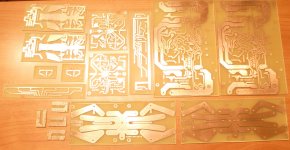
After a short (30+ years) break in PCB making...
As title says, the last PCB that I made was 30+ years ago and it was done using letraset (and marker). Now, thanks Dr. Bora Jagodic (boraomega) and Viktor Bradjan (viktor1986) for being patient with me, providing schematics and PCB layouts, as well as Sylvain Bergeron (algar_emi ) for support to make my own PCB from the scratch, here is what I done couple of days ago. These small buggers on the lower left side are made first (I guess that you can tell) so I am not that proud of them, but rest is not that bad.
To make them like that I used a photo exposure process. All layouts are printed (twice) on transparent sheet, using a laser printer. Photo sensitive boards are exposed for about 8 minutes under the UV light, then immersed in developer for 5-10 minutes to remove exposed parts and finally etched using Ferro chloride.
Before drilling I made a small guide hole (using several nails), then drill them using a Dremel drill with drill press and carbide drills. The small (0.8mm) drill broke after 20 holes but I wanted to see will broken one still work, and it did B-)
Am I happy with result, well, you should see the wrinkled smile on this old farts face B-))
And now real fun begins…
Attachments
Very nice!
For your drill press, you can probably stop breaking bits if you take a long spring and connect it on one side on the back part of the drill (on the part that doesn't move) and pull it around the front of the part (that does move up and down) and then connect it to the other side of the back part (that doesn't move). It should take most of the "play" out of the drill press itself. I used to break them at least every 200 holes or so. But now I can usually get about 2000 holes, before I accidentally break the bit by hitting it with something.
For etchant, you would probably MUCH prefer this type that you can make yourself, using "always available" chemicals, by adding one part hydrochloric acid (sold at hardware stores and at swimming pool chemical suppliers in the USA as Muriatic Acid) to two parts of the common 3% Hydrogen Peroxide, as sold at pharmacies et al.
Oh, also, just put the drill guide holes on your PCB artwork and etch them out. That works perfectly to guide the drill bit into them.
Have fun!
i used to use water as a drill bit coolant. it also keep the fiberglass dust from becoming a dust cloud. where the water works excellent for bit cooling is when drilling aluminum. it's difficult to drill aluminum with a dremel tool, because you get a thin layer of molten aluminum that the bit just spins around in without penetrating much. add some water to cool the bit and workpiece, and the bit just bites through the aluminum in no time. this also makes the bit last longer because the steel doesn't anneal and become soft.
- Status
- This old topic is closed. If you want to reopen this topic, contact a moderator using the "Report Post" button.
- Home
- Design & Build
- Parts
- To Make Good PCB at home