Dear SYMASYM-friends,
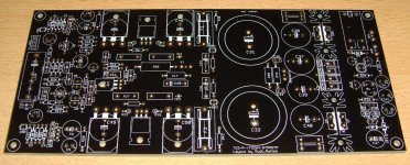
I have received a pair of Birger's SYMASYM-PCBs - as a gift - yesterday (image 1). The PCBs are of excellent quality.
What I do not like (but: this depends) is the silkscreen.
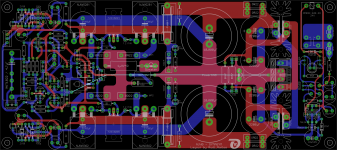
Birger is using "components' names", whereas I have always been using "components' values". Find the values' silkscreen attached (image 2).
Do not forget to manually solder a wire to connect SignalGND to PwrGND (painted in turquoise).
I have also attached the drill-template that can either be used for TO3-P output transistors as well as for TO-264 output transistors (see attached .pdf - file).
Best regards - Rudi_Ratlos
I have received a pair of Birger's SYMASYM-PCBs - as a gift - yesterday (image 1). The PCBs are of excellent quality.
What I do not like (but: this depends) is the silkscreen.
Birger is using "components' names", whereas I have always been using "components' values". Find the values' silkscreen attached (image 2).
Do not forget to manually solder a wire to connect SignalGND to PwrGND (painted in turquoise).
I have also attached the drill-template that can either be used for TO3-P output transistors as well as for TO-264 output transistors (see attached .pdf - file).
Best regards - Rudi_Ratlos
Attachments
It's more useful to have both component number and component value silk screened on top.
Even better if both can be not obscured by the in place components.
Unfortunately this requires a lot of space. I would opt to have the value obscured rather than lose the label (if I have to choose).
Component number also silked on bottom for testing voltages is nice to have.
Even better if both can be not obscured by the in place components.
Unfortunately this requires a lot of space. I would opt to have the value obscured rather than lose the label (if I have to choose).
Component number also silked on bottom for testing voltages is nice to have.
Rudi, Thank you for the silkscreen and the drill template. For the people who ordered your BB's at Birgers website the template was indeed missing. Perhaps you would be so kind to post the schematic for this version too. The schematic on page 32 of the builders manual is rather blurry when you enlarge it to read the numbers and values. At the moment I'm waiting anxiously for the boards to arrive.
On the PCB that's precisely where the CT is connected. Far left-hand side closest to C38-C40. I suppose Rudi could have put a GND symbol on the left instead of the middle.Rudi and all.
The centre tap labeled GND should be connected to the extreme left hand end of the long horizontal Zero Volts, not in the middle as in backend.pdf
Good, that the PCB is correct.On the PCB that's precisely where the CT is connected. Far left-hand side closest to C38-C40. I suppose Rudi could have put a GND symbol on the left instead of the middle.
Bad, in that the sch is misleading.
Hey guys,
regarding the silkscreen, I just was not aware that Rudi always orders the values layer. For me it's not a problem, I will order what the audience wishes")
(nevertheless I prefer names layer, as the values are changing from time to time...)
Unfortunately the first batch of PCBs is sold out, and the second is already ordered. But for the future boards I can order the silkscreen as you like.
regarding the silkscreen, I just was not aware that Rudi always orders the values layer. For me it's not a problem, I will order what the audience wishes
(nevertheless I prefer names layer, as the values are changing from time to time...)
Unfortunately the first batch of PCBs is sold out, and the second is already ordered. But for the future boards I can order the silkscreen as you like.
Hello Birger,
I prefer the Names in the silkscreen. This is better for debugging/maintenance. But in this case it would be better if the Names are placed beside the parts.
Is it possible to print both, the values under the parts and the names beside of it?
Regards Thomas,
already got one pair of this BB PCBs
I prefer the Names in the silkscreen. This is better for debugging/maintenance. But in this case it would be better if the Names are placed beside the parts.
Is it possible to print both, the values under the parts and the names beside of it?
Regards Thomas,
already got one pair of this BB PCBs
Birger, I prefer the "silkscreen with values" - of course!
The reasons:
First: I am a lazy DIYer.
I don't want to look at the PCB to get the name of a component, then look at the schematic and find(!) the component within the schematic, get its value from the schematic and check,
if it makes sense to insert this component on this position.
I simply look at the PCB, get a component with the specified value on the silkscreen from one of my components' boxes and solder it.
Second: the SYMASYM - BB - PCB's values' silkscreen is absolutey perfect.
You can rely on the silkscreen - components' values!
There is only one exception: you need to distinguish between using an "active" or a "passive (attenuation only)" PRE.
In case you are using an "active" PRE, you need to solder a couple of resistors that are used on the input differential pair of transistors to lower the overall gain of the SYMASYM.
In case that you are using a "passive" PRE, you have to replace these resistors by 0r0 (i.e. wires) resistors.
I myself did not hear any difference between "active" and "passive" SYMASYM, being driven by a "passive" PRE.
Third: my desktop is crowded by component boxes, soldering iron, tools, a glass of whisky, ...
I wonder where to put the sheets (images) with the schematic, with "silkscreen with values", ...
That is why I vote for the "Value Silkscreen".
Best regards - Rudi_Ratlos
Except for a few obvious parts the value doesn't really tell you anything about the 'type' of component. And, I'm not talking about the difference between resistors and caps. If you were in doubt (which is my case many times), you have no true cross reference for that value - visually on the PCB. Take for instance an e-cap... In the case of the Symasym, I don't recall the voltage rating being printed along side the value for e-caps. And, there were some e-caps of identical values, but different voltage ratings. If you had the part number/name then you could simply cross-reference that single part number to the BOM and BE SURE you've selected the correct e-cap with the proper voltage rating. For those of us less skilled in this hobby and consider ourselves 'solder monkies', this method seems almost fool-proof in getting the correct component solder in the right place, the first time - albeit with a little more work up front looking at the BOM. I'd much rather get it right the first time than to have to de-solder a component and retro-fit the proper one. However, in fairness to Rudi, and the Symasym, he did provide a printed solder-mask of the PCB with the names for each part.
Just my 2 cents worth.
Rick
However, in fairness to Rudi, and the Symasym, he did provide a printed solder-mask of the PCB with the names for each part.Just my 2 cents worth.
Rick
I think that's a valid assumption.if "valve" was meant to read value then the current count is
name 3
value 2
- Home
- Group Buys
- TO-3 SYMASYM