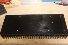
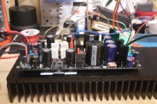
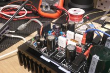
Got the heatsinks (HS) drilled and tapped tonight. Here's a couple of pictures showing the results with some brass standoffs and the amp just seating on the HS.
The boards themselves are almost done save the input caps, input configuration for an active pre and the output devices. It's been slow, but it is progress.")
Rick
The boards themselves are almost done save the input caps, input configuration for an active pre and the output devices. It's been slow, but it is progress.
Rick
Attachments
So if I had some good 2,200mfd laying around at the correct voltage I'm good to go?If You look on the schematic see that they are connected on the positive and negative rails so minimum voltage is the rail voltage for this sitiation 50v caps will suit. 470uf is ok but 1000uf sounds even better as local power reserve.
Rick
Last edited:
Rudi,In my opinion they are fine
Sent from my Nexus 5 using Tapatalk
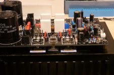
Why not solder the output devices from the component side of the PCB once you've securely screwed them down and you've properly aligned the leads with the PCB and lowered it into place. There are nice big solder pads on top too. The only one that may be a challenge is the BD139. I was even thinking of leaving the leads on as test points for the devices should it be necessary.
I know it's the not the most elegant looking, but is there something I'm overlooking as to why you may not want to do this?
Rick
Attachments
Rick, i did it the same way you propose and it seems the moste reliable way to be sure everything is in place and alligned. After transistors are tight on heatsink and pcb is in place i dont see any problem to solder it and after that you can melt some solder on the other side if you want.
I dont understand why Rudi recommend the oposite, i am really interested to know the reason from Rudi.
Adrian
I dont understand why Rudi recommend the oposite, i am really interested to know the reason from Rudi.
Adrian
I just thought that without self-stick thermal pads it might be a bit dicey lining up the pad with the device under the PCB. Not impossible, but more difficult. Since Rudi used self-stick pads that makes it significantly easier. This is my first amp build where the transistors are under the HS. Once you start soldering, you're rather committed to having it right!
The only thing we can really test prior to attaching the PCB to the devices is the PSU - without the fuses in-place of course. Just enough to see if the DC voltages are in line. Correct?
Rick
The only thing we can really test prior to attaching the PCB to the devices is the PSU - without the fuses in-place of course. Just enough to see if the DC voltages are in line. Correct?
Rick
Rick: I wonder how you will solder the 1.000µF caps on top of the output transistors (unless you lift them a bit of course).
Do not forget to solder the 2 wires beneath the PCB (NFB and Signal-to-PowerGND).
Use a light bulk, when you "test" the backend PSU.
Measure the resistance between any pin of the output-transistors and drivers and the heatsink.
Make sure that the trim potentiometer is set to its maximal value.
Do not insert the fuses, but use 10 Ohm resistors to power up the frontend. The frontend consumes <15mA, so 0.25 wattage resistors will do it.
Keep your fingers crossed, have a glass of wine or whisky - and power on.
Best regards - Rudi
Rudi,Rick: I wonder how you will solder the 1.000µF caps on top of the output transistors (unless you lift them a bit of course).
Do not forget to solder the 2 wires beneath the PCB (NFB and Signal-to-PowerGND).
Use a light bulk, when you "test" the backend PSU.
Measure the resistance between any pin of the output-transistors and drivers and the heatsink.
Make sure that the trim potentiometer is set to its maximal value.
Do not insert the fuses, but use 10 Ohm resistors to power up the frontend. The frontend consumes <15mA, so 0.25 wattage resistors will do it.
Keep your fingers crossed, have a glass of wine or whisky - and power on.
Best regards - Rudi
Thanks the punch list of final things to check and do. I have been carefully reading your build guide so as not to overlook anything that would be difficult to correct. I've never used the light bulb trick, but I do intend to with this amp.
I have not soldered the PCB into place yet, as there are a few more parts to place, including the 2 wires on the back side. But as can be seen in my earlier picture, I have all the leads lined up perfectly, so hopefully during the final fitting the PCB will slip right into place and I'll solder from above.
Regarding the 1000mfd caps... I thought about soldering them in place normally (upright), before mounting the PCB. It would still give me room to solder the transistor leads from the top, but I may decide to lay them horizontally to make a bit more room. I don't have those caps yet in hand, but they are on their way. I'll have to wait and see how their size fits before making a final decision.
I haven't fried an amp yet, and I don't think it will happen this time. Fingers crossed.
Next weekend may be power on time! Rick
If the input resistor is 82k to 100k, then a 1uF cap gives an LF roll off about a decade below the 20Hz start of the Audio band.
A 1uF MKP, or MKT, will cost much less than $11.30
If one retains the 22k for the input resistor to suit BJT LTP, then you are stuck with 4u7F for the decade wider passband.
However if the jFET LTP were adopted, then there is no reason to use the 22k input resistance. Use 82k, or 91k, or 100k.
@AndrewT- in FC-100 amp are also used the 22k and 2sk170 input transistors. Should i use the same aproach with 100k resistors ?
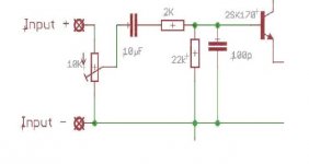
What is the purpose of 2k resistor in series with input signal ?
Attachments
Last edited:
the 2k+100pF is a low pass filter. It attenuates RF interference
the 10uF+(2k+22k) is a high pass filter. It attenuates extreme LF interference and blocks DC from a bad source.
The 10k unbuffered vol pot adds in a variable resistance that creates extra filtering effects, that vary with vol pot setting.
You really should have a buffer at the vol pot to present the power amplifier input with a low source impedance.
But you shouldn't put the buffer circuitry inside the amp enclosure. Correct?....You really should have a buffer at the vol pot to present the power amplifier input with a low source impedance.
if you require the amp input to see a low value source impedance that does not change significantly when you change settings, then yes you would use a Buffer on the vol pot.
If the amp performance is very tolerant of changing the source impedance then a local vol pot would not need a Buffer.
If the amp performance is very tolerant of changing the source impedance then a local vol pot would not need a Buffer.
Correct, the Buffer generally does not get added to the receiver, it is needed at the transmitter.But you shouldn't put the buffer circuitry inside the amp enclosure. Correct?
It's still not clear to me what the values should be for R40 and R42 in the back-end PSU circuitry. They are labeled on the Black Beauty PCB as 1 Ohm, yet the schematic is calling for .47 Ohm. Which is it, or doesn't it matter.
I mistakenly soldered .1 Ohm so was wondering if that value is way to low and should I parallel them with a 1 Ohm to get .55 Ohm.
Rick
I mistakenly soldered .1 Ohm so was wondering if that value is way to low and should I parallel them with a 1 Ohm to get .55 Ohm.
Rick

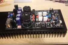
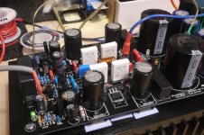
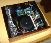
We have Lift-off!
More progress made on my Symasym build today. It's been a wet, soggy and cool weekend, here in New England and with the girls gone I made some significant headway on my project.
Following Rudi's excellent build guide, I applied power and with the PSU supplying the correct voltages, I set out to make sure there were no issues by using the 10R resistors as fuses. Once i confirmed that, I put in the fuses and adjusted the voltages to ~ 24.5ma across the emitter resistors.
I let it run for about 30 minutes and then adjusted the other channel. When everything checked out as I expected it would, I plugged in my minidisc player and heard audio for the first time on the Black Beauties! Clean, pure audio. Of course I was only using my bench speakers, so no critical listening has been done yet. I love it when there are no issues.
Attached are a few pics.
Attachments
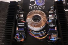
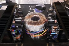
Rick, my case is a little bit bigger than yours, and I am using a customer-specific toroid transformer with 4 secondaries @25VAC rated at 400VA.
The price of this transformer is the same as the price of 2 toroids with 2 secondaries each.
Enjoy the SYMASYM's sound - Rudi
The price of this transformer is the same as the price of 2 toroids with 2 secondaries each.
Enjoy the SYMASYM's sound - Rudi
Attachments
Is there any problem in feeding my two channels with the same secondaries in a parallel or daisy-chain type arrangement?Rick, my case is a little bit bigger than yours, and I am using a customer-specific toroid transformer with 4 secondaries @25VAC rated at 400VA.
The price of this transformer is the same as the price of 2 toroids with 2 secondaries each.
Enjoy the SYMASYM's sound - Rudi
Also, in my final layout that can be seen in the pics, is my xformer too close to the circuitry where there may be some inductance issues?
Rick
- Home
- Group Buys
- TO-3 SYMASYM