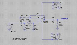
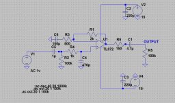
you mean like that ?
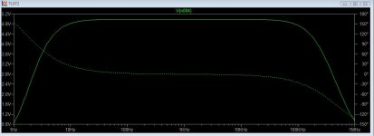
That looks OK. 1k and 330pf gives a -3db point of nearly 340kHz. Decoupling caps can be as low 0.1uf and added close to the power pins of the IC. Adding a single cap across the pins (4 and 8) can be just as effective at suppressing instability and has the advantage that no rail noise is injected into the signal grounds.
Last edited:
Why not try the inverting amplifier ? It is not so noisy as the non-inverting version.
I have attached below an example of where you work to start. The results can be amazing.
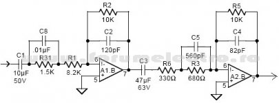
What is the function of C5 and C8 ?
You could still decrease R1 and R3 as Andrew suggested earlier, this can improve noise performance. I'd also decrease the input impedance 100k resistor to some like 22-33k and increase the coupling cap as required.
The output coupling cap may not be required at all but if it is bear in mind that a subsequent stage might be well under 100k input impedance and so your bass performance would suffer. Spec this cap according to the next stage input impedance, if in doubt make it large, but in theory it isn't needed at all.
I've been using the OPA2227 recently and found it nice to work with and perfectly clear. A bit like the OPA2134 overall, it's got strong drive like the 5532, super low THD+noise and also the output offset is usually unmeasurable, so that helps with my previous point.
The OP has not specified what his idea of a "simple preamp" is.
* Is a volume control needed?
* What sort of minimum input impedance is required?
* What kind of input levels are expected?
* What kind of output levels is it supposed to produce?
* How much output noise would be acceptable?
* How is it supposed to be powered?
Someone who wants a fixed-gain level booster for their wimpy mobile device will have different requirements than someone who needs a classic hi-fi preamp.
Both the TL072 and the NE5532 prefer inverting over noninverting operation by a significant margin for various reasons, but it is virtually impossible to get both high input impedance and low noise at the same time in an inverting configuration (noise gain is signal gain + 1 to begin with, and high input impedance would require high resistor values which also means high voltage noise). When going inverting, I would generally prefer a two-stage design (~6 dB plus ~6-10 dB) with volume pot in between, at least as far as the classic hi-fi preamp goes.
sgrossklass
the preamp i am going to build i am going to put it in a Marantz 2250B reciever .
My knowledge in electronics is limited .
could you or some else recommed me stage gain about a X5
with Hi Fi ability ?
i see that donpetru recommend me a ciricut . but it has to many componets i want it simplier and good though .
Your circuit in post #20 is fine. You could usefully add a small series resistor between the opamp output and C1 (to isolate the opamp from external capacitance). Use something between around 39 and 82 ohm. C1 could also be increased a little depending on the impedance the opamp is working into. There's noting wrong with using an electroylitic either, fit the polarity according to the measured voltage across the cap... it could be either way depending on the opamp used.
Both the TL072 and the NE5532 prefer inverting over noninverting operation by a significant margin for various reasons,
Could you explain reasons? I know that CM distortions will be somewhat lower but that is not good enough reason to invert phase and add another stage.
Does adding a buffer made of an emitter follower combined to a constant current source make a TL071/2 a much nicer device ?
I wouldn't have said so tbh. The TL071/2 is a nice device if you use it properly.
5x gain with no nothing (no tone controls and stuff)?sgrossklass
the preamp i am going to build i am going to put it in a Marantz 2250B reciever .
My knowledge in electronics is limited .
could you or some else recommed me stage gain about a X5
with Hi Fi ability ?
i see that donpetru recommend me a ciricut . but it has to many componets i want it simplier and good though .
Let's see what's inside the good ol' Marantz right now...
Gah, why do their schematics always have to be such a mess?

Oh boy, there's an old, old BA312 amplifier IC in there (not even an opamp, just a 3-transistor affair). And a 250k volume pot (and 500k balance) - anyone in need of some hiss? And an inverting Baxandall tone control with switchable time constants. Single supply, of course (a little under +35 V).
Modifying this thing would be a huge mess - you'd basically have to scrap the entire preamp section (pots included) and come up with a new single-supply preamp circuit. I suggest you build an external preamp for it instead - use a tape output to get the input signals out of there (via the record selector) and go back in at the Main input.
Note that the power amp only has about 23 dB of voltage gain and could use up to about 19 dB (9x) of preamp gain for 150 mV of input sensitivity, like the original circuit has. 16 dB (6-6.5x) would probably be OK, too.
You wouldn't happen to have a little headphone amplifier floating around, like a cMoy? One of those would be quite well-suited. 10k-22k pot, 5532, gain setting resistors 5.6k and 1k or so, and RCA outputs rather than the headphone jack. Basically the single-supply version with one 9V battery would do (and one could consider "borrowing" the +35V supply from the Marantz if it's not too much hassle), though one with split supply (two 9V blocks, DPDT power switch) would perform better. It's not a very power-hungry circuit and ought to run for 25-40 hours or so on one set of batteries.
I wouldn't have said so tbh. The TL071/2 is a nice device if you use it properly.
Using a unity gain buffer at the output of an integrated op-amp avoids great variations of current inside the package with low ohmic loads. This seems in agreement with the philosophy expressed by Stan Curtis in Linear Audio Volume #6 and 7 which consists to prevent interferences by mutual induction between wires. In an integrated circuit, the output is in very close proximity to the other stages, some sonic benefits should occur if it has ever only a minimum of current ever deliver.
Does adding a buffer made of an emitter follower combined to a constant current source make a TL071/2 a much nicer device ?
You asked the question
I wouldn't have said so tbh. The TL071/2 is a nice device if you use it properly.
I'll stand by my above comment.
Using a unity gain buffer at the output of an integrated op-amp avoids great variations of current inside the package with low ohmic loads. This seems in agreement with the philosophy expressed by Stan Curtis in Linear Audio Volume #6 and 7 which consists to prevent interferences by mutual induction between wires. In an integrated circuit, the output is in very close proximity to the other stages, some sonic benefits should occur if it has ever only a minimum of current ever deliver.
Everyone has their own ideas and ways of doing things... there is no right and wrong approach. I would ask if you can tell a difference in a proper DBLT (double blind listening test). If you can genuinely pick and prefer the additional components in the above circuit, then I would be looking to see if simply using a different opamp (such as an LM4562) rendered those additional parts as unnecessary, or whether the same improvement carried through using that opamp.
In order of importance:
You don't show proper power supply decoupling, there needs to be a 10nF or greater ceramic type cap on each supply rail right at the op amp supply pins to a low impedance ground.
R4 and C4 should be mounted on the input jack for greatest effect, and C4 should be grounded to chassis.
R6 would be better around 47 to 100 ohms.
C1 output cap is probably not necessary, but if you need it, make it more like 10uF so that when you connect a normal load like 10k ohm the bass won't suffer.
Mike
Last edited:
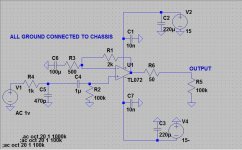
That looks OK. When you put it together keep loop areas small, i.e. mount the bypass caps close to the chip as mentioned before, the feed back resistor should also be close to the chip. Connections for input, output and power should be twisted pairs/triples.
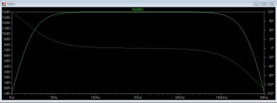
I just noticed that the f3 of your feed back network is a little high-ish (3.2 Hz), so you might want to increase C6 to something like 220uF. Or you could just double the value of the feed back resistors with only a VERY small increase in noise and accomplish the same thing.
Mike
I just noticed that the f3 of your feed back network is a little high-ish (3.2 Hz), so you might want to increase C6 to something like 220uF. Or you could just double the value of the feed back resistors with only a VERY small increase in noise and accomplish the same thing.
Mike
Last edited:
because it is old amplifier all ground connected to chassis .
what do you think now ? thanks
How are you going to power this seeing as the amp is single rail ? Do you understand the difference ?
(as I mentioned earlier, you can easily make this a single rail design if you want)
- Status
- This old topic is closed. If you want to reopen this topic, contact a moderator using the "Report Post" button.
- Home
- Source & Line
- Analog Line Level
- TL072 VS NE5532