Hi Dennis,
On our original design for the toolereg we had onboard mounted heatsinks and big MKP’s as output cap but the PCB is quite large and appears no to be very user friendly when trying to fit it to say a CDP and this is when we thought that a Compact version could serve as more universal application. For this to come true we needed to leave out the HS’s and the big output cap.
In the other hand, if we are using the reg to power say B1’s, NS10’s or other circuits (class A) that will draw say 50mA or less there seems to be no need to shunt more current than some 50mA or a bit more, maybe up to 100mA and not much HS is needed for this. I think a small alu bar or L shape piece or the small “flying” sheet alu HS will be enough. In other words we need to tailor them for the application. Yes, the chassis HS might be a bit more involved since the tranies are not to the edge of the boards but some lead shapping will most probably solve this.
Dennis, are you still available to manage the GB?
")
On our original design for the toolereg we had onboard mounted heatsinks and big MKP’s as output cap but the PCB is quite large and appears no to be very user friendly when trying to fit it to say a CDP and this is when we thought that a Compact version could serve as more universal application. For this to come true we needed to leave out the HS’s and the big output cap.
In the other hand, if we are using the reg to power say B1’s, NS10’s or other circuits (class A) that will draw say 50mA or less there seems to be no need to shunt more current than some 50mA or a bit more, maybe up to 100mA and not much HS is needed for this. I think a small alu bar or L shape piece or the small “flying” sheet alu HS will be enough. In other words we need to tailor them for the application. Yes, the chassis HS might be a bit more involved since the tranies are not to the edge of the boards but some lead shapping will most probably solve this.
Dennis, are you still available to manage the GB?
apassgear said:
In the other hand, if we are using the reg to power say B1’s, NS10’s or other circuits (class A) that will draw say 50mA or less there seems to be no need to shunt more current than some 50mA or a bit more, maybe up to 100mA and not much HS is needed for this. I think a small alu bar or L shape piece or the small “flying” sheet alu HS will be enough. In other words we need to tailor them for the application. Yes, the chassis HS might be a bit more involved since the tranies are not to the edge of the boards but some lead shapping will most probably solve this.
Dennis, are you still available to manage the GB?
Hi Tony,
Thanks for your comments.
And yes, I'm still available to manage a GB.
Cheers,
Dennis
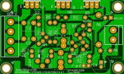
I just wanted to keep the traces as large as they were on your design. And there is not enough room between the feet of the T0220 drekk ...
But maybe 3mm is overkill and we could go somewhat smaller traces.
Then, there ll no need for traces on top side ...
Sorry if I make things complicated ...
Manuelito
But maybe 3mm is overkill and we could go somewhat smaller traces.
Then, there ll no need for traces on top side ...
Sorry if I make things complicated ...
Manuelito
Attachments
Dennis Hui said:
And yes, I'm still available to manage a GB.
Cheers,
Dennis
Well thats great Dennis, wanted to hear that
From my side I have no objection and appreciate your cooperation to set up this GB so here is the baton

Cheers
Manu said:
Sorry if I make things complicated ...
Manuelito
Not at all Manuelito, it just call my attention and of course we can live those there.
Manu said:Is that what you meant concerning the shuntreg?
Manu
This way the board would be 1 mm smaller
Yesssss!!!!
That looks excellent Manolo, well done… and smaller too.

smaller, may not be better
Gentlemen,
Great work, nice board, especially as suitable for +/- and the accompanying "raw supply" pcb.
I would suggest you re-consider the idea of trying to compress the already small pcb - a couple of extra mm isn't going to make much difference if the possibility of slightly larger/better caps will improve it's performance. ( the larger PP's do sound better, but can possibly add them externally to the O/P terminal blocks )
Also, really only need one support on side away from the T0-220 trannsistors side, even if use a "heatsink", and nylon supports for isolation.
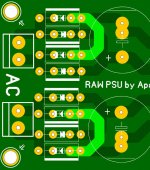
On the "raw supply", suggest you fit in a resistor between diodes and ripple cap - not "fashionable" today, but does make a difference and an easy option to include.
Where do you expect the central "Star Earth" to be located (including pre input signal earth, and output) at the regulator input, output or at the raw supply, and do you want to "float this off chassis earth with a resistor, etc on the supply pcb, reg pcb, etc? (ie extra terminals?)
... my 2 cents!
Gentlemen,
Great work, nice board, especially as suitable for +/- and the accompanying "raw supply" pcb.
I would suggest you re-consider the idea of trying to compress the already small pcb - a couple of extra mm isn't going to make much difference if the possibility of slightly larger/better caps will improve it's performance. ( the larger PP's do sound better, but can possibly add them externally to the O/P terminal blocks )
Also, really only need one support on side away from the T0-220 trannsistors side, even if use a "heatsink", and nylon supports for isolation.
On the "raw supply", suggest you fit in a resistor between diodes and ripple cap - not "fashionable" today, but does make a difference and an easy option to include.
Where do you expect the central "Star Earth" to be located (including pre input signal earth, and output) at the regulator input, output or at the raw supply, and do you want to "float this off chassis earth with a resistor, etc on the supply pcb, reg pcb, etc? (ie extra terminals?)
... my 2 cents!
Bonus Supply
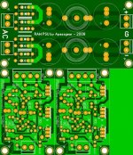
To use that empty space we have on the board I have prepared a Bonus Raw Supply, Super Compact may I add, which could be quite usable on those tight places we some times run into.
The layout is based on the very small inductor from MuRata 22R473C (DK 811-1293-ND) that Twitchie suggested, in this case I have two of them, one to each leg but you decide to use a jumper on one of the sides.
Rather small caps but enough for some 200mA; on those sizes you may find 2,200 and 1,000uf caps. The rest will be done by the regulator itself.
Manu, your prayers have been answered
Do you think is doable?
Attachments
Welcomed James,
Lots of good points there, I don’t want to repeat what I already answered to Dennis (post 382) so the Compact version is just that, for a more universal application that can also be used on tight places.
I agree with you that MKP might be better but we decided the replace these with good quality polyester at the output but retain MKP’s on C1 and C3 that are more important in my view. BTW, Steen has tested these regulators with all polyester caps and found no detrimental issues there, so it might be one of those cases of diminishing returns. And of course we always have the possibility to add external components as mention, cumbersome but doable when we have the space.
We added four holes for support screws in case someone wants to use the power tranies on an upright position; well, 4 fixing point will give more mounting flexibility to use two or more screws, as you already noted the board is quite small.
Diode snubbers have to be tuned to the load you will be using and need some test equipment to do this to get some useful action from them, on my point of view a bit cumbersome. In the other hand the raw supply and the reg board forms a CLCLC filtering (if we count the ferrite bead) which should get rid of RF and nasties from the diode bridge plus the fact that the supply board is separated from the shuntregs, we did this at the early stage of the PCB development just to provide added isolation.
As usual one has to decide where to put the Star Ground and depends on what you will be using these. For a preamp one can send the returns from the regs to the SG and from the preamp itself to the SG…. And float a ground to chassis from the SG the way you prefer.
Cheers
Thanks Tony'
Yes, that about covers all the little things quite well and as you said, it is a compakt design and can add some externals if the fancy takes us.
This combination boards is a very neat package and it's quite a lot of work.
Many thanks for your efforts and especially for providing the finished design for a group buy - it is very much appreciated.
apassgear said:Aren't you missing the connection to R7?
Nope ... it is just masked by the upper trace between the 2 trannies ...
Manu
Our baby is now full as an egg ..
T0220 diodes freaks : There are extra pins for this purpose on RAW supply kiddoe ... crowded but it should work ...(hopefully)
Manu
James : provided that is doesn't implies too much changes to existing PCBs I can provide a board (as PDF for home etching) which fits your special needs ...
An externally hosted image should be here but it was not working when we last tested it.
T0220 diodes freaks : There are extra pins for this purpose on RAW supply kiddoe ... crowded but it should work ...(hopefully)
Manu
James : provided that is doesn't implies too much changes to existing PCBs I can provide a board (as PDF for home etching) which fits your special needs ...
Bonus supply
Menu and Tony,
You guys are great. The bonus supply would be
great for something like the B1 and has much
utility on its own.
I was going to suggest using that PCB space for
making a couple of Diyaudio key chains, but
the supply board is much more useful.
Thanks,
Dennis
Menu and Tony,
You guys are great. The bonus supply would be
great for something like the B1 and has much
utility on its own.
I was going to suggest using that PCB space for
making a couple of Diyaudio key chains, but
the supply board is much more useful.
Thanks,
Dennis
- Status
- This old topic is closed. If you want to reopen this topic, contact a moderator using the "Report Post" button.
- Home
- Amplifiers
- Pass Labs
- Threshold NS10 Lineamp PCB