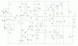
Fair enough, but it really doesn't matter... In the following circuit, the 6V6 doesn't GAF if that TVS is there or not... Without that SA12CA, the MOSFET quickly turns into a wire (especially without RY1!). A lot of MOSFETs have a protection diode built in anyway...
RY1 is drawn incorrectly. It shorts the MOSFET G-S for 10 seconds, then opens. There's no connection to ground.

RY1 is drawn incorrectly. It shorts the MOSFET G-S for 10 seconds, then opens. There's no connection to ground.
Can you tell us more?My only beef with the gate protection is that the fet inputs will see all of the capacitance of the TVS diodes, since they are essentially being operated at 0V. I have a scheme that biases up the protection zeners to reduce the capacitance they present to the diff amp gates, and keep them out of the way until they actually encounter an ESD event..
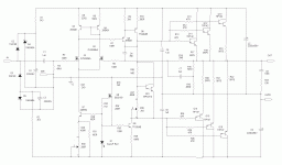
Here's a sample circuit using an n-channel enhancement mode differential front end. The diodes connected to the input are already low capacitance in nature, but still more so, as they are reverse biased by about 15V. The capacitor and zener backing the diodes help absorb ESD energy. So, it's definitely more parts than a pair of zeners/TVS, but a lower and more controlled capacitance directly connected to the input. If you're feeling a mite paranoid, you can use larger diodes at the input instead of the 1N4148. The larger diodes will still have reduced capacitance due to the reverse bias.
Attachments
On the SV83: Francois G asked about this article a couple weeks back. I have it on paper and was able to find it on the Wayback Machine: https://web.archive.org/web/20040206202049/svetlana.com/docs/TechBulletins/appnoteNo.29.html
Maybe it's been found already? Easier for me just to post it. The Wayback Machine is great.
Maybe it's been found already? Easier for me just to post it. The Wayback Machine is great.
I don't understand why my post illustrating an alternate clamp circuit for a mosfet front end was deleted, as it was in response to a poster that was using back-to back zener clamps for a mosfet diff stage feeding a tube output. Yes, it was an SS amp but it was illustrating an alternate clamp circuit for a mosfet differential front end.
Fair enough, but it really doesn't matter... In the following circuit, the 6V6 doesn't GAF if that TVS is there or not... Without that SA12CA, the MOSFET quickly turns into a wire (especially without RY1!). A lot of MOSFETs have a protection diode built in anyway...
RY1 is drawn incorrectly. It shorts the MOSFET G-S for 10 seconds, then opens. There's no connection to ground.
View attachment 1135636
unsolicited advise, please start a thread about this as this invited off topic discussion...
Sorry you feel that way... I thought it was relevant to the thread. We were talking about MOSFETs and how some people think strapping a TVS diode across gate and source destroys the circuit or something...
If you don't, report it and see if the administration will remove it.
If you don't, report it and see if the administration will remove it.
I don't like putting a nonlinear junction capacitance across the inputs of my projects. Tubes are nicer that way, as the capacitance comes from pieces of metal separated by a vacuum - pretty much the most linear capacitor there is...
i agree...
I've been trying to understand output stage loadlines lately. The loadlines posted by kodabmx on page 88 of this thread go way above the max power curve. Is this acceptable (and typical?) because it's push-pull class AB, and it's the average power that matters? If I had class A push pull, would It be recommended to stay below the max power curve?
Yes and yes.I've been trying to understand output stage loadlines lately. The loadlines posted by kodabmx on page 88 of this thread go way above the max power curve. Is this acceptable (and typical?) because it's push-pull class AB, and it's the average power that matters? If I had class A push pull, would It be recommended to stay below the max power curve?
Best regards!
Same here, and I posted my questions above too.I've been trying to understand output stage loadlines lately. The loadlines posted by kodabmx on page 88 of this thread go way above the max power curve. Is this acceptable (and typical?) because it's push-pull class AB, and it's the average power that matters? If I had class A push pull, would It be recommended to stay below the max power curve?
As I understand it the difference between these sweep tubes and normal pentodes is that the g2 winding is not shielded by the g1 winding, so the g2 is as much a plate as the anode, but with much reduced current handling capability. To tame those tubes it is not just the current flow in the g2 that is to be considered, but also the interaction between the g2 and the whole tube.
I built a clone of the Tubelab SPP with PL84 tubes, and even being within the published characteristics I had red-plating issues. I also discovered that maximum specs were not the same in different manufacturers' data sheets so an effective design needs to assume the lowest common denominator. The TV tubes were developed for roles in standard TV chassis and were tested with that in mind. They were one trick ponies.
- Home
- Amplifiers
- Tubes / Valves
- Those Magnificent Television Tubes


 Restored, they were deleted because someone reported them as off topic.