Some interesting trivia on the 6LQ6 versus 6JE6 thing.
The original RCA 6LQ6 spec came out in 1967 when the GE 6JE6B came out. Both have the same plate curves as the original RCA 1962 6JE6 . (except for a small kink at low current in the 6JE6B, gone in the 6JE6C)
The 1967 RCA 6LQ6 appears to be what the later Sylvania 6JE6C would be in 1968 (plate boxlets, and winglets on at least the 6JE6C, maybe both had the winglets).
Except the 6LQ6 had RCA's new "dark heater" which only needs 2.3 Amps at 6.3V, instead of 2.5 Amp. However, a typo on the 6LQ6 datasheet left the current at 2.5 Amp. In 1969 RCA came out with the 31LQ6 and they corrected the 6LQ6 datasheet heater current to 2.3 Amp., as being a typo on the earlier one.
So the only difference between a 6JE6C and a 6LQ6 is the heater current discrepancy and using black insulating ceramic on the 6LQ6 heater wires.
I went and looked at the Sylvania 24JE6A/24LQ6 tubes I have, and they have the old white ceramic insulated heaters, but draw 0.63 Amps at 24V, which would correspond to 2.4 Amp at 6.3 V. So they are right between the equiv. 6LQ6 2.3 Amp spec and the 6JE6C 2.5 Amp spec. They have the plate boxlets and winglets of the 24/6JE6C.
I also went and looked at some 21LG6A tubes I have (GE 1967 registered). These only draw the equiv. of 2.0 Amp 6.3V heaters. ( The -LG6 is rated at a lower 28 Watt and 315 mA max DC versus the 6JE6C/6LQ6 at 30 Watt and 350 mA max DC. But 2.0 Amp is still proportionately lower. )
The Sylvania ones have white ceramic heater wires, the GE ones have gray ceramic heater wires, and the RCA ones have black ceramic heater wires.
The 21LG6A has very close to the same plate curves as the 6JE6C/6LQ6 and has the boxlets and winglets too, and costs about 1/10 as much. It uses a 12 pin Compactron base versus the 9 pin Novar base of the 6JE6C/6LQ6.
I'm sure you're all thrilled to be let in on this trivia, but you never know when you'll get quizzed on it. It's long been a puzzle to me why the 6LQ6 existed beside the 6JE6. They both fit the same socket and have the same curves.
Last edited:
The TV Sweep tubes do have a low Rp in triode mode (like 313 Ohm for 21LG6A) but often not spectacularly good triode curves. The 21LG6A does have noticeable curve "rollover" in its triode curves (a common ailment for Sweeps), which would cause noticeable 2nd Harmonic dist. in SE mode.
The other bigger problem is the low voltage rating for grid 2. Some Sweeps can develop runaway current after operating above g2 spec for extended periods in triode configuration.
The latest cure for all this is to use the "new" series Schade (or UnSET, CED at Tubelab). This fixes the g2 V problem, and also the curve "rollover" problem. (and one can adjust how much 2nd H one wants left in by using some Schade on grid 2 as well) The output power can be increased another 20% or so too, since the cathode driver power adds to the tube's power output.
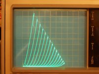
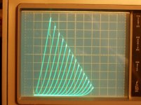
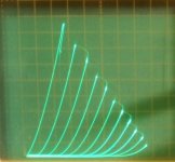
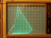
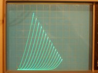
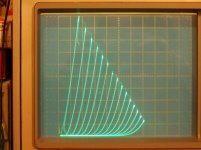
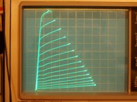
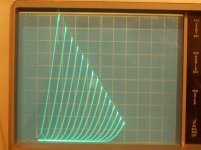
Pics below of 21LG6A in native triode mode, then a similar 6HJ5 in "new" series Schade mode. Then a 21HB5A in the "new" series Schade with the triode "rollover" really knocked out and also 21HB5A in ordinary triode mode.
And finally 6HJ5 in standard triode mode (can see almost same as 21LG6A in triode).
Looking at that 6HJ5 in series Schade (21LG6A a very similar tube) I'm seeing a 211 that can do Amperes at reasonable B+ and OT Zpri.
50V/div Horiz., 50mA/div Vert.
a) GE 21LG6A in triode mode -8V steps
b) Syl 21LG6A in triode mode -8V steps
c) 6HJ5 in "new" series Schade (UnSET, CED)
d) 21HB5A in "new" series Schade (UnSET, CED)
e) 21HB5A in standard triode mode
f) 6HJ5 in standard triode mode
The other bigger problem is the low voltage rating for grid 2. Some Sweeps can develop runaway current after operating above g2 spec for extended periods in triode configuration.
The latest cure for all this is to use the "new" series Schade (or UnSET, CED at Tubelab). This fixes the g2 V problem, and also the curve "rollover" problem. (and one can adjust how much 2nd H one wants left in by using some Schade on grid 2 as well) The output power can be increased another 20% or so too, since the cathode driver power adds to the tube's power output.
Pics below of 21LG6A in native triode mode, then a similar 6HJ5 in "new" series Schade mode. Then a 21HB5A in the "new" series Schade with the triode "rollover" really knocked out and also 21HB5A in ordinary triode mode.
And finally 6HJ5 in standard triode mode (can see almost same as 21LG6A in triode).
Looking at that 6HJ5 in series Schade (21LG6A a very similar tube) I'm seeing a 211 that can do Amperes at reasonable B+ and OT Zpri.
50V/div Horiz., 50mA/div Vert.
a) GE 21LG6A in triode mode -8V steps
b) Syl 21LG6A in triode mode -8V steps
c) 6HJ5 in "new" series Schade (UnSET, CED)
d) 21HB5A in "new" series Schade (UnSET, CED)
e) 21HB5A in standard triode mode
f) 6HJ5 in standard triode mode
Attachments
Last edited:
Pentode mode will have rather high output Z and obvious 2nd harmonic dist. unless some Neg. Fdbk is used. Limited Global Neg. Fdbk could get you similar results to the "new" series Schade scheme (UnSET, CED), but it will require more attention to stability (going thru the OT) than the local N Fdbk of series Schade.
UL mode will get you in between pentode and native triode. More 2nd harmonic and higher Zout than native triode.
After seeing the spectacular results of "new" series Schade (UnSET, CED) I consider all of those to be obsolete now. (pic below)
----------------------------
Lets see, where are those 40KG6/PL509 tubes I was going to trace.....
I better get those done before the big ICE STORM from Texas gets here and the power fails. Brrrr...
Attachments

Last edited:
Well, a number of 6CB5 SETs have been done. (6CB5A triode curves below. They look about the same as 21LG6A, 6HJ5 or 6JE6C in triode) I don't know if anyone has used them in pentode with N. Fdbk. Search on 6CB5.
George (Tubelab) has a thread on UnSET here:
UNSET is coming?
It is essentially just conventional Schade (R1 from plate to grid 1 and another R2 from grid 1 to GND, or to a Neg. bias V. These set the "triode" gain. R1 = Mu x R2 ) EXCEPT the drive signal is moved to a P Mosfet Follower at the cathode, with some biasing at the Mosfet gate.
807 etc should work, just have to keep the drive voltage swing in mind for the P channel Mosfet follower. (P Mosfets around are more limited voltage than the usual N channel ones, but there are high V ones up to 500 V I think. Need to keep gate and reverse transfer (Miller) capacitance low too. P chan Mosfets typically have higher gate and Miller capacitance, so selection important, and the previous driver stage can't be wimpy. )
Attachments
Last edited:
I have some Fairchild FQP1P50 that I use, but I don't know if these TO-220 packages are available any more. Might be something available in a different package. Well, looks like DigiKey has them. You will need some gate stopper resistors with these, oscillate without any power.
google FQP1P50. DigiKey came up, but something won't let me post the link.
google FQP1P50. DigiKey came up, but something won't let me post the link.
Looks like that one is OOP. Found this one
https://www.mouser.com/datasheet/2/308/FQP3P50-D-1809684.pdf
500v. but I don't know what parameters we would want for this duty.
https://www.mouser.com/datasheet/2/308/FQP3P50-D-1809684.pdf
500v. but I don't know what parameters we would want for this duty.
This is the thread in Tubelabs subforum.
UNSET is coming?
I quote, from post 75
So here you have the ICs you need. I actually got the FQPF9P25, as I like their fullpack isolation. Another comment. I don't know the amount of current in the LND150 used by George, but as TO92 I do not think there is more than 1-2mA going through that concertina, so it is not a very strong driver.
UNSET is coming?
I quote, from post 75
The phase inverter in the 50C5 amp is a Microchip LND150 in TO-92, and the output stage gets a Fairchild / ON Semi FQP3P50. There are probably better choices than the 3P50 in that output stage, but I had a bunch and they worked.
The big powered amp gets Fairchild FQPF9P25's since they are the only part that I haven't blown up, and you know how big my power supply is. Bad stuff happens when it gets hungry, especially when running at full crank. Yes, SOA is the big thing here, followed by the usual Crss and Gm. I pick a Vds spec with some margin above the voltage needed to fully cutoff the output tube under the expected operating conditions, and current capabilities beyond what the tube should handle.
So here you have the ICs you need. I actually got the FQPF9P25, as I like their fullpack isolation. Another comment. I don't know the amount of current in the LND150 used by George, but as TO92 I do not think there is more than 1-2mA going through that concertina, so it is not a very strong driver.
I asked because George also reveals the P fet he uses in the driver stage, in the same post 75.
I am going down this route, looking forward for some experience exchange!
The actual part I have been using in my input stages for everything from the 50C5 amp to the 250 watt 36LW6 monster is the Microchip VP0106 in a TO-92 package. Anything similar in a breadboard / PC board friendly package should work.
I am going down this route, looking forward for some experience exchange!
Yes, timing is good. I am not using a splitter so my driver will be single ended. I was just wondering because the LND150 is rated at 3ma max source to drain.
I plan to simulate it in LTSpice so I can play with parameters. But I am kind of blind on the basis for the silicon selection.
I plan to simulate it in LTSpice so I can play with parameters. But I am kind of blind on the basis for the silicon selection.
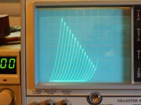
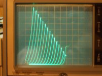
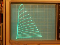
I finally got to tracing the 40KG6/PL509 tubes. All pretty similar, USA or Japan types.
Voltage on grid 3 (beam plate here) didn't have much effect. +30V rounded the knees just slightly, and -30V moved the knees right to just slightly higher plate voltage. Beam plates (as opposed to an actual -grid- 3 ) don't generally have much effect with added voltages, and these tubes look to be already optimized for the sharpest knees.
The RCA tube had narrow boxlets and the usual winglets. The Panasonic tube had narrow boxlets and a very abbreviated winglet, but an extended width support strip instead. The Panasonic also had big grid 1 cooler fins up top.
50V/div Horiz., 50mA/div Vert. for all:
a) RCA pentode -1.5V steps on grid 1, 81V on grid 2
b) RCA in triode mode -7V steps
c) Panasonic pentode -1.5V steps on grid 1, 76V on grid 2
d) Panasonic in triode mode -7V steps
Attachments
Last edited:
"I finally got to tracing the 40KG6/PL509 tubes"
smoking-amp I've taken a screen-snip of #1438 and saved it forever in my OneDrive.") .
.
So a well designed TV Beam pentode the 40KG6/PL509.For best performance just tie Sg3 tied to its cathode.Those Barks are doing a good job aren't they!
So you had to break open a valve to view its internals..no?
Now to find a suitable SE output transformer.....no deep pockets here. Ta very much for your work.
smoking-amp I've taken a screen-snip of #1438 and saved it forever in my OneDrive.
.So a well designed TV Beam pentode the 40KG6/PL509.For best performance just tie Sg3 tied to its cathode.Those Barks are doing a good job aren't they!
So you had to break open a valve to view its internals..no?
Now to find a suitable SE output transformer.....no deep pockets here. Ta very much for your work.
Hi Smoking-amp!
Could you do a trace of the Pl509, using the g2 as anode? With max power 10 W or something? I did that a few years ago by hand but the ink faded grrrrr. I read somethiing about a low power amp that used them that way and it seemed to be very linear. Also, one could fool arond with some voltages on A for some fine-tuning.
Thanks!
- Home
- Amplifiers
- Tubes / Valves
- Those Magnificent Television Tubes