 .
.Yes, as far as I see it, he mainly relates to LS/GU50 tubes, hence common pentodes. Smoking-amp in contrary said he didn't notice major differences with more recent sweeps, such as the 40KG6, with beam plates and Barkhausen chambers in the anode structure and, possibly, aligned control and screen grid wires.
Best regards!
Best regards!
Hi Smoking-amp!
Could you do a trace of the Pl509, using the g2 as anode? With max power 10 W or something?
Kay Pirinha
You are right, but because G2 in not surrounded by a hot anode I think it will survive more.
Think of those tiny, brittle grid wires.
I'd not try it, but I'd also see no real use for it. Best regards!
The thermal mass of the plate structure is huge compared to the thermal mass of a single grid wire.
The peak dissipation in the plate can exceed the ratings by a factor of two or three as long as the average power being dissipated is below spec.
This is not true of the grid wires. I have found that a screen grid wire can blow like a small fuse rather quickly if overheated since it takes too long to cool, especially in the center where it is closest to the cathode and right in the middle of the electron beam.
You might get away with brief music peaks over 7 watts, but continuous sine wave testing will blow the grid wires. This is why I abandoned screen driven sweep tubes years ago.
I checked several 40KG6's here with a magnifying glass and they all have aligned grids. Looking at the spec data of 1400 mA/45 mA confirms that as well.
Using some additional data scribbled in my GE handbook (can maybe check with the traced triode curves) I see at 100 mA: pentode Rp is 5700 Ohms, gm is 10500 and Mu is 3.57. So triode Rp (Rg2) is 340 Ohms versus pentode Rp of 5700 Ohms. 340/5700 = 0.0596 or 6%. So running as a triode with only g2 would raise the triode curves Rp by 6% to 360 Ohms, not much. So the triode curves as given earlier are pretty close to what you would get with grid 2 only as the plate. I have to agree with the others that burning up grid 2 is a real possibility.
Grid 2 and the plate both have near 3/2 power transfer functions, so there is not going to be any qualitative difference in the curves. The near 4/2 power law at grid 1 (due to wire proximity effect to cathode, mis-matching the 3/2 power at the "plate" ) is what determines the roll-over (2nd H dist.) in the curves.
I don't have any 6P45S tubes, they cost more now than the real things (40KG6)! If you want to send one over for curve tracing, I would be happy to do so.
The GU50 has a real grid 3, which does work well for squaring up the knees.
The -45V on the beam plate 3 of the 6KG6's in the "Traynor YBA-3A" bass amp Davorin posted apparently is to round off the knees a little for less harsh clipping, would be my guess.
Last edited:
Would the 21LG6A be suitable for an SE amp or it hopelessly relegated to AB1 PP duty?
The 21LG6 like most TV sweep tubes has a rather low maximum screen grid voltage rating. Attempting to connect them in triode mode (screen tied to plate) will usually lead to failure. Some older sweep tubes will live in triode mode at reduced plate voltage, but my experiments with anything made since the 1960's had lead to blown tubes. They die of a slow cook death at idle where the screen grid sits at plate voltage for an extended time. Eventually one tube will go into a runaway condition which can get ugly in tubes that can conduct over an amp of plate current.
What about 21LG6 in SE pentode-ish mode?
I don't have any 6LG6 or 21LG6, but I spent about a year stuffing just about any tube I could find into Pete Millett's Engineers Amp with good success. Every sweep tube I tried worked fine. I saw 525 watts flow out of one of those boards with both channels wired in parallel using 35LR6's. That design runs the output tubes in pentode mode with some output tube plate to driver plate (Schade) feedback to lower the THD and output impedance. The details are scattered throughout the long thread. My board first made sound in post #138:
Posted new P-P power amp design
Ok sold! Can you point to a link of a topology using one of these sweep tubes as an example?
I see you have found it, and I will try to organize the two UNSET threads a bit better in the coming week or two. Unfortunately I have been guilty of scattering my work across several threads in the tubes and the Tubelab forum. I will try to get as much of it as I can find into the two UNSET threads in the Tubalab forum. Personal circumstances have kept my workbench dark since mid December.
Would this work also in a non-sweep tube like an 807?
I have not tried an 807, but an 807 is a 6L6GA which I have tried, along with 6L6GC's and KT88's. They work fine with appropriate screen grid voltages and some resistor value tweaks.
Can you please suggest a good mosfet to use for the cathode drive? I assume from reading the linked thread that I do not need a negative supply in this arrangement?
The mosfet under the output tube must be capable of handling the peak current seen in the output tube as it's driven into hard conduction. In some sweep tubes this can be well over 1 amp. The voltage across the fet is low at this moment. Conversely the fet can see over 100 volts across it at low current. Unfortunately most of the mosfets made today are designed for switching applications, and not linear operation. The SOA for linear operation is often not specified (no curve for DC) or just plain wrong. If the DC curve is equal to the rated dissipation, it's likely wrong. This is the case for most ON Semi / Fairchild devices.
The fet will be sitting in a linear region at idle, and not all fets can take it. I test possible fets with a power supply at 2 or 3 X what they will see in an amplifier. In a follower application the Crss should be as low as possible, since this is what the driver tube sees.
The FQP3P50 has been used successfully in small amps, up to 40 watts or so. It has a low 9.5 pF Crss that can be directly driven by the LND150 phase splitter. For bigger amps I am using the FQPF9P25. Those live at power levels of 300 watts in a push pull 36LW6 amp.
Same for the driver tube mosfet? Or would there be a better choice there than the FQP3P20? Or just stick with the LND150?
The driver tube mosfet only sees a few mA and maybe 30 volts. There are dozens of possible choices here, so I picked five or six good ones, bought some, and prepared to test them in the board. The first one worked better than I expected, so I never got to the test. It is the Microchip VP0106.
Yes, timing is good. I am not using a splitter so my driver will be single ended. I was just wondering because the LND150 is rated at 3ma max source to drain. I plan to simulate it in LTSpice so I can play with parameters. But I am kind of blind on the basis for the silicon selection.
The LND150 is used for the phase splitter in my little 50C5 amp. According to my data sheet it is good for 30 mA and my amp runs it at a bit over 3 mA. It will NOT work in the driver circuit as it is an N channel device.
I tend to use whatever silicon devices in my sims that are in the LT spice library, then put whatever parts that I can actually get into my prototype designs. The proto may have different parts than the sim, but they have worked pretty close to the sim so far.
Re: PL802 about getting a SET OT
As George (Tubelab) just mentioned:
The 40/6KG6/PL509 may not get along for long in a simple triode wired setup. Better to use the series Schade/UnSET/CED thing so that grid 2 can operate within spec, and the triode curves are even more linear.
a) 40KG6 triode
b) 6HJ5 triode
c) 6HJ5 UnSET
As George (Tubelab) just mentioned:
The 21LG6 -like most TV sweep tubes- has a rather low maximum screen grid voltage rating. Attempting to connect them in triode mode (screen tied to plate) will usually lead to failure. Some older sweep tubes will live in triode mode at reduced plate voltage, but my experiments with anything made since the 1960's had lead to blown tubes. They die of a slow cook death at idle where the screen grid sits at plate voltage for an extended time. Eventually one tube will go into a runaway condition which can get ugly in tubes that can conduct over an amp of plate current.
The 40/6KG6/PL509 may not get along for long in a simple triode wired setup. Better to use the series Schade/UnSET/CED thing so that grid 2 can operate within spec, and the triode curves are even more linear.
a) 40KG6 triode
b) 6HJ5 triode
c) 6HJ5 UnSET
Attachments
Last edited:
Assuming the Svetlana EL509/6KG6 is the same as the 6P45S, you would have some pentode curves below.
However, one mystery occurs, since those curves are NOT the same as an Amperex 6KG6. They look the same, but the screen voltage for the Svetlana tube would need to be increased by 1.5x versus the Amperex to get the same plate currents. This would mean the internal Mu factor would be 1.5x that of the Amperex also.
https://frank.pocnet.net/sheets/084/6/6KG6.pdf
Attachments
Last edited:
Yeah, I remember when Svetlana had Amp designs.
--------------------------------------------------------------------
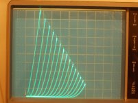
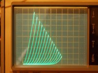
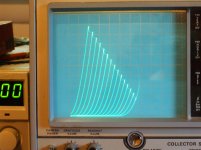
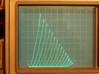
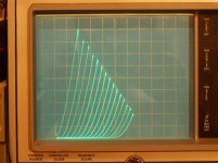
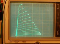
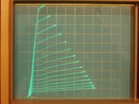
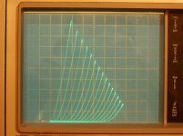
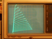
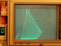
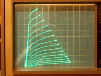
Today's mail brought the long awaited Davorin mysterious "winged" RCA 6DQ5s and a couple of 6P41S too. The tubes were labelled 102 and 145 mA, so I've kept those labels here. The emission for the two was different as you can tell.
Here are the "winged" 6DQ5s.
50V/div Horiz., 50 mA/div Vert.
a) 102 pentode -2V steps on grid 1, 100V on grid 2
b) 102 in triode -6V steps on grid 1
c) 102 in triode -8V steps on grid 1
d) 145 pentode -2V steps on grid 1, 97V on grid 2
e) 145 in triode -8V steps on grid 1
for comparison with the usual 6DQ5:
f) Rayheon (Japan) traditional 6DQ5 pentode -2v steps, 110V on grid 2
g) Raytheon (Japan) traditional 6DQ5 triode mode -6V steps
h) Sylvania (USA) traditional 6DQ5 pentode -2V steps, 110V on grid 2
Well, i would say they don't fit the traditional 6DQ5 curve sets as far as kinks go.
They have the minimised kinks of the later Sweeps with plate boxlets. These "winged" tubes do have the plate boxlets and winglets. The plates are gray, but the winglets are black. Hadn't seen that combo before. Could easily be a 6LG6 or 6JE6C or 6JS6/6HF5 or similar inside, or could just be a plain ol' 6DQ5 with all the "BLING" of the later tubes added on. You all can try to match them up. Fun, fun!!
Some tube "suspects" curves back on page 142
--------------------------------------------------------------------
Today's mail brought the long awaited Davorin mysterious "winged" RCA 6DQ5s and a couple of 6P41S too. The tubes were labelled 102 and 145 mA, so I've kept those labels here. The emission for the two was different as you can tell.
Here are the "winged" 6DQ5s.
50V/div Horiz., 50 mA/div Vert.
a) 102 pentode -2V steps on grid 1, 100V on grid 2
b) 102 in triode -6V steps on grid 1
c) 102 in triode -8V steps on grid 1
d) 145 pentode -2V steps on grid 1, 97V on grid 2
e) 145 in triode -8V steps on grid 1
for comparison with the usual 6DQ5:
f) Rayheon (Japan) traditional 6DQ5 pentode -2v steps, 110V on grid 2
g) Raytheon (Japan) traditional 6DQ5 triode mode -6V steps
h) Sylvania (USA) traditional 6DQ5 pentode -2V steps, 110V on grid 2
Well, i would say they don't fit the traditional 6DQ5 curve sets as far as kinks go.
They have the minimised kinks of the later Sweeps with plate boxlets. These "winged" tubes do have the plate boxlets and winglets. The plates are gray, but the winglets are black. Hadn't seen that combo before. Could easily be a 6LG6 or 6JE6C or 6JS6/6HF5 or similar inside, or could just be a plain ol' 6DQ5 with all the "BLING" of the later tubes added on. You all can try to match them up. Fun, fun!!
Some tube "suspects" curves back on page 142
Attachments
-
 6DQ5_RCA102_wing_T_50V_50mA_8V.jpg666.6 KB · Views: 53
 -
 6DQ5_RCA102_wint_T_50V_50mA_6V.jpg655.1 KB · Views: 228
 -
 6DQ5_RCA102_WING_50V_50mA_2v_100V.jpg643.6 KB · Views: 233
 -
 6DQ5_RCA145_WING_50V_50mA_2V_97V.jpg659.1 KB · Views: 52
 -
 6DQ5_RCA145_Wing_T_50V_50mA_8V.jpg629.1 KB · Views: 58
 -
 6DQ5_RAY_50V_50mA_2V_110V.jpg619.5 KB · Views: 50
 -
 6DQ5_RAY_T_50V_50mA_6V.jpg637.3 KB · Views: 50
 -
 6DQ5_SYL_50V_50mA_2V_110V.jpg645.9 KB · Views: 48
Last edited:
Correction to post 1454 above.
Apparently the Svetlana 6GK6/EL509 was a 6P42S, not the 6P45S of interest now.
That explains the grid 2 voltage discrepancy.
both of the 6P42S and the 6P45S are being sold as 6GK6/EL509, substitutes maybe Anatoliy might have something to say about this...
Care should be taken when using the 6P42S tube as the base connection is the same as for the EL500 / EL504 / 6GB5 / 6P44S / 6P36S tube and not as for the EL505 / EL509 / EL519 / 6KG6 / 6KG6A.
There are also 2 types that differ in the mechanical structure and performance of the glass balloon, although they are the same according to the measured static data.
One type completely resembles the 6P45S in the appearance of the internal mechanical structure, but the other type differs in everything and even the size of the plate-anode is somewhat smaller.
- Home
- Amplifiers
- Tubes / Valves
- Those Magnificent Television Tubes