I think a lateral mosfet headamp is long over due, especially for the classic headphones like AKG Sextettes that were designed around a mosfet output but they need more voltage than +-12V.
I was able to get my hands on a set of 2SK2013 / 2SJ313.
Can you share the simulation so I can work out the substitution and higher rails ?
I already sent you the files several weeks ago.
")
Also the 2SK2013/SJ313 are not lateral FET's, they dont look like it looking at the datasheet. They wont fit the output FET PCB footprint either since they are GDS while 2SK1058/2SJ162 are GSD. Also there is no thermal compensation in my design since the Lateral FET's don't need it.
Why dont you just stick with the 2SK1058/2SJ162 that I have used and increase the rails to +/- 18V? That is the maximum that the DC servo opamp can handle. Should provide you with a little over 12V RMS which is 240mW into a 600R load.
Last edited:
I already sent you the files several weeks ago.
Also the 2SK2013/SJ313 are not lateral FET's, they dont look like it looking at the datasheet. They wont fit the output FET PCB footprint either since they are GDS while 2SK1058/2SJ162 are GSD. Also there is no thermal compensation in my design since the Lateral FET's don't need it.
Why dont you just stick with the 2SK1058/2SJ162 that I have used and increase the rails to +/- 18V? That is the maximum that the DC servo opamp can handle. Should provide you with a little over 12V RMS which is 240mW into a 600R load.
I apologize, been working 80 hrs a week, just getting caught up. 12V rms would be perfect.
Where are you finding the 2SK1058/SJ163 ?
Thanks with your patients, and thanks for the PCB/project.
Edit: just found 5 pairs for $30 buck on ebay. Looks like a decent alternative to the 2sj76, 2sk213 which are expensive as heck nowdays.
thanks again.
Last edited:
I apologize, been working 80 hrs a week, just getting caught up. 12V rms would be perfect.
Where are you finding the 2SK1058/SJ163 ?
Thanks with your patients, and thanks for the PCB/project.
Edit: just found 5 pairs for $30 buck on ebay. Looks like a decent alternative to the 2sj76, 2sk213 which are expensive as heck nowdays.
thanks again.
I bought them from reichelt.de in Germany.
You can get them from ampslab.com in the US.
I actually looked at the 2SK213/2SJ76 Lateral FET's when doing some preliminary design work on my headphone amplifier and there was a few reasons I didn't pick them instead of the bigger and more powerful 2SK1058/2SJ162, one reason being availability, another being price.
Last edited:
Well, sometimes **** hits the fan.
The basic design is good, however I might have been a little too focused on getting very low THD-20 distortion numbers at the cost of stability in some cases.
2 test headphones worked very well, but my own cheap Sennheiser HD415 headphones caused some instability. Switching the 2 compensation caps from 10pF to 39pF fixed it right up. THD-20 went from 0.0005X% to 0.0008X% in simulation with 5.6V p-p output.
So I would advise anything from 39pF to 150pF as compensation caps. 150pF still gives a low THD-20 0f 0.001X% in simulation with 5.6V p-p output.
If you want to be on the 100% completely safe side then use 150pF, otherwise lower values could work just as well, depending on your headphone and the headphone cabling.
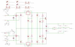
Revised schematic attached.
PS : It sounds absolute fantastic with just a pair of cheap Sennheiser HD415 headphones.
I don't know whether you were asked this question elsewhere in the thread, but have you considered altering that beta-multiplier based compound VAS in to it's non-compound version by bypassing the VAS input emitter followers? While this should improve the stability by reducing the VAS open-loop gain, what I'm really wondering what subjective listening difference might be.
I don't know whether you were asked this question elsewhere in the thread, but have you considered altering that beta-multiplier based compound VAS in to it's non-compound version by bypassing the VAS input emitter followers? While this should improve the stability by reducing the VAS open-loop gain, what I'm really wondering what subjective listening difference might be.
You could go with a non darlington VAS and it would probably improve stability somewhat at the cost of slightly higer THD-20 numbers. It would most likely sound about the same.
Going further, you could even leave out the drivers and drive the Lateral FET's directly from the non darlington VAS if you wanted to. But performance would most likely suffer and it wouldn't be the same amp anymore.
However, after I increased the compensations caps to 39pF stability has been a non-issue. The amp has been rock solid.
There is many ways to make a great headphome amp and I won't pretend that my way is the only way. But it works and I am happy with the result.
Last edited:
I sincerely hope that my comment did not sound critical of your design. It certainly wasn't meant to sound that way . I applaud all who risk ridicule by exposing their designs with the rest of us . It's just that my limited past experience with the beta-multiplier (darlington, as you call it) has been that it tends to be a focal point for stability issues.
. I applaud all who risk ridicule by exposing their designs with the rest of us . It's just that my limited past experience with the beta-multiplier (darlington, as you call it) has been that it tends to be a focal point for stability issues.I sincerely hope that my comment did not sound critical of your design. It certainly wasn't meant to sound that way
I didn't take it the wrong way, so no problems from my side.
You are quite right that more gain could lead to stability issues, unless you compensate the circuit accordingly.
What you call a beta-multiplier is essentially a darlington coupling.
Last edited:
What you call a beta-multiplier is essentially a darlington coupling.
Although the Darlington and the beta-follower both consist of cascaded BJTs, a Darlington is usually taken to be a cascaded emitter-follower (grounded-collector), while a beta-multiplier is a compound grounded-emitter transistor. The beta-follower comfiguration creates a very high current gain grounded-emitter composite amplifier, where the net current gain (beta) is the product of the two individual BJT's current gains .
.
Last edited:
Although the Darlington and the beta-follower both consist of cascaded BJTs, a Darlington is usually taken to be a cascaded emitter-follower (grounded-collector), while a beta-multiplier is a compound grounded-emitter transistor. The beta-follower comfiguration creates a very high current gain grounded-emitter composite amplifier, where the net current gain (beta) is the product of the two individual BJT's current gains .
Well, looks like you might be right. What I have used is usually called a darlington VAS but in reality it would only be a real darlington coupling if the collectors of both transistors were connected together. I connected the collectors of the first transistors to ground so they are not real darlingtons as they are normally used. But you still get the same current gain as if it were a real darlinghton coupling.
Atleast that is how I understand it.
Last edited:
While I am waiting on the mosfets, I was looking at these newish ortho headphones. This Thor was originally intended for me a a "replacement" to using old Sansui recievers to power 600 ohm AKG's. But this amp may also be an excellent cost effective amplifier for these new current hog orthos.
But this amp may also be an excellent cost effective amplifier for these new current hog orthos.
The amp modules should have no problem delivering transients of several amps, provided that the power supply is up for it.
Not that you would ever want to put several amps through your headphones, even for short transients.
But as with many other things, it doesn't hurt to have power in reserve.
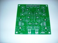
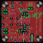
Here is a rather crappy picture of a supply board PCB.
I completed a board today and so far it looks like it works.
However I only sent +/- 20VDC through it, so the real test is not before Monday when I can hook up my transformer to it.
If everything goes well, I should be able to test everything together on Monday, that means amp boards, supply board and no-thump board all connected together in my modushop alu case.
Attachments
Just playing around with LtSpice simulations, testing the amp at no load(10Meg) and with a 32 Ohm load I get some interesting results.
Output impedance of around 0.00114 Ohm and damping factor of around 28K with a 32 Ohm load.
Unloaded(10Meg) shows peaks of 2.7795V which equals 1.98546099V RMS
32 Ohm loading shows peaks of 2.7994V which equals 1.98539007V RMS
Calculating damping factor : (1.98546099/(1.98546099-1.98539007)) equals 27995.7838
Calculating output impedance : 32/27995.7838 equals 0.00114302926 Ohm
Made an error :
"Unloaded(10Meg) shows peaks of 2.7795V which equals 1.98546099V RMS"
2.7795V should have been 2.7995V.
The rest is correct.
A good paper on 0-Ohm impedance headphone amplifiers and the benefits they provide. 0-ohm-headphone-amplifier-sonic-advantages-low-impedance-headphone-amp
"Unloaded(10Meg) shows peaks of 2.7795V which equals 1.98546099V RMS"
2.7795V should have been 2.7995V.
The rest is correct.
A good paper on 0-Ohm impedance headphone amplifiers and the benefits they provide. 0-ohm-headphone-amplifier-sonic-advantages-low-impedance-headphone-amp
Last edited:
Well, hooked it all up today, no smoke, humm or buzz and it sounds great.
Only problem is my No thump board, the AC detection doesn't work as it should, it doesn't work with AC applied to the AC detect connector. DC fine, AC no go.
I'll have to figure out the issue tomorrow, but to be honest I'm rather puzzled by it.
Simulation works absolutely 100% and similar AC detect circuits has been used with success for years by many others.
But I'll have a solution sometime tomorrow.
Edit : Think I have an idea why it doesn't work, but I'll look into it tomorrow
Last edited:
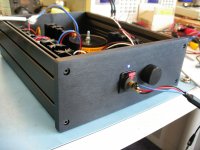
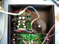
Got everything hooked up.
It works and it sounds great. No hum or buzz. No pop/thumps/crackles when turning on and no squealing/whizzing and similar noises when turning off.
Looks like everything is good to go.
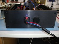
What is left now is mounting the IEC inlet(with filter) in the backplane as well as the Neutrik RCA connectors and then solder the few wires I have left.
It works and it sounds great. No hum or buzz. No pop/thumps/crackles when turning on and no squealing/whizzing and similar noises when turning off.
Looks like everything is good to go.
What is left now is mounting the IEC inlet(with filter) in the backplane as well as the Neutrik RCA connectors and then solder the few wires I have left.
Attachments
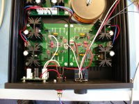
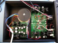
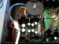
Like I mentioned in a previous post, I had an issue with my No Thump board where a transistor had to be turned 180 degrees. The first picture I have attached shows that transistor.
Also, my AC detection didn't work. Well, I found the problem, I connected the AC detection wire going to my No Thump Board, to the wrong secondary on the Supply Board. Attached picture number 2 shows what is the wrong connection and what is the right connection.
Also, my AC detection didn't work. Well, I found the problem, I connected the AC detection wire going to my No Thump Board, to the wrong secondary on the Supply Board. Attached picture number 2 shows what is the wrong connection and what is the right connection.
Attachments
- Status
- This old topic is closed. If you want to reopen this topic, contact a moderator using the "Report Post" button.
- Home
- Amplifiers
- Headphone Systems
- Thor, an all discrete Lateral FET Headphone Amplifier.