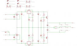
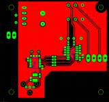
This is my final supply design.
Going back to the LM317/LM337 design + cap multiplier after some more simulation. It just works better.
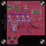
2 star ground points, first star ground handle the rectifiers, B1/B2 as well as the first caps, C1/C2. The rectified AC current in these components is not something you would want to pollute your ground connection with so these currents should be resolved locally. This first star is connected to the main star ground point where all other grounds lead to.
On the picture that main star ground point might look huge but in reality it is only 14mm x 6mm so it is just exactly the size needed to get all grounds hooked up to it with decent size tracks.
This is the supply design that will be going into production once I get the last few issues sorted out, mainly silkscreen and tidying up the layout.
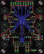
Going back to the LM317/LM337 design + cap multiplier after some more simulation. It just works better.
2 star ground points, first star ground handle the rectifiers, B1/B2 as well as the first caps, C1/C2. The rectified AC current in these components is not something you would want to pollute your ground connection with so these currents should be resolved locally. This first star is connected to the main star ground point where all other grounds lead to.
On the picture that main star ground point might look huge but in reality it is only 14mm x 6mm so it is just exactly the size needed to get all grounds hooked up to it with decent size tracks.
This is the supply design that will be going into production once I get the last few issues sorted out, mainly silkscreen and tidying up the layout.
Attachments
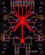
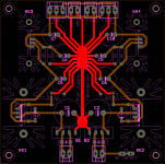
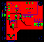
I think you should group the negatives at X4 and the positives at X3.
All the outputs will be closer to the output caps and less loss through
the traces. Otherwise, I like the layout quite well.
Maybe the main ground trace could be a little thicker in the middle.
A few extra centimeters does not matter much, besides, there are 2200uF on each rail on the Thor amp boards so it is a non issue.
Realizing that people might want to drop 5-10V across the LM317/LM337 regulators, depending on the transformer used, the heatsink size has been increased substantially. Should handle up to 5W dissipation without too much trouble, that is a voltage drop of 10V across the regulators with 500mA output current.
Attachments
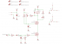
Been looking into a balanced input version of Thor MKII.
It can be done but you dont really gain much. If you have a source with only balanced out, just leaving the -Out unconnected and using +Out and GND should work just as well. Changing Thor MKII to balanced is not worth it. Distortion rises quite alot, although it is still very low, requires a few more components and overall just isnt worth the hassle.
Balanced in consumer audio is more marketing than anything else. Just keep the interconnects short and as far away as possible from anything noisy, like mains cable and other similar things that could inject noise into your interconnects.
Anyway, thats my personal opinion on the issue.
If you really, really want balanced, just get 4 amp modules and be done with it. Better in every way, except size and price.
Last edited:
hmm noise i can understand, distortion...? something doesnt sound right
Was just a quick and dirty non optimized simulation.
I could probably get the distortion down to singe-ended input levels but still, I dont really see the point.
If you want balanced, then do it right from the beginning, which means 4 separate channels to make one balanced stereo amp.
The other option with a balanced input works, but the amp would still not be balanced.
Either go single ended all the way or go balanced all the way.
With some luck the No-thump boards should arrive sometime next week, which means I'll be able to get it mounted and tested before the weekend. Should work great.
Anyway, the supply boards are on their way as well and I already got all the components needed to make a single board.
Exciting times, but the waiting is killing me.
Anyway, the supply boards are on their way as well and I already got all the components needed to make a single board.
Exciting times, but the waiting is killing me.
Last edited:
I made a little board with a WM8804 SPDIF receiver, ESS9023 DAC, volume pot, 3.3V regulators, onboard rectifier.
Needed something better than what a crappy onboard soundcard can deliver.
I'm not pretending this is a highend DAC setup but anything is better than what I get from onboard sound from my computer.
Toslink input only, should support atleast up to 24/96, depending on the toslink input bandwidth and general quality.
Gerber top and bottom.
Attachments
Last edited:
I made a little board with a WM8804 SPDIF receiver, ESS9023 DAC, volume pot, 3.3V regulators, onboard rectifier.
Needed something better than what a crappy onboard soundcard can deliver.
I'm not pretending this is a highend DAC setup but anything is better than what I get from onboard sound from my computer.
Toslink input only, should support atleast up to 24/96, depending on the toslink input bandwidth and general quality.
Gerber top and bottom.
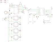
Interesting ... Can you attach a schematic diagram?
Interesting ... Can you attach a schematic diagram?
Attachments
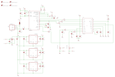
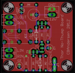
Got my No-Thump boards yesterday and today I assembled a board and tested it. Came as no surprise that it worked, 10 Sec delay before the relay is on.
However, I made a little error. T1 is a BC557 transistor and for some reason I chose a TO-92 EBC transistor as my model. BC557 is usually CBE which meant I had to rotate it 180 degrees before my board worked. Took a liltte while before I realized it. But a few measurements and the problem was found.
Luckily it doesn't affect the No-thump board performance, only consequence is visual, with the transistor being turned 180 degrees compared to the silkscreen.
Compared to the schematic attached below there is a small change. R1 with a value of 1Meg only gives 2 Sec. turn on delay, what I used was a 5M1 resistor for the 10 Sec. delay metioned a few lines above.
Attachments
Last edited:
") )
)I think a lateral mosfet headamp is long over due, especially for the classic headphones like AKG Sextettes that were designed around a mosfet output but they need more voltage than +-12V.
I was able to get my hands on a set of 2SK2013 / 2SJ313.
Can you share the simulation so I can work out the substitution and higher rails ?
I was able to get my hands on a set of 2SK2013 / 2SJ313.
Can you share the simulation so I can work out the substitution and higher rails ?
- Status
- This old topic is closed. If you want to reopen this topic, contact a moderator using the "Report Post" button.
- Home
- Amplifiers
- Headphone Systems
- Thor, an all discrete Lateral FET Headphone Amplifier.