it would take up less room
It might take less room, but then my heat sinks would get smaller and I need them all.")
Placing transformer under is more elegant way, don't forget also about the AC entry/filtering board. The amps seems to be better balanced too (mechanicaly).
One other thing: the front end board goes between capacitor banks, so if I put transformer there it would be really tight.
Chris,
I added the extra caps because by removing active regulators I had extra space. The current is about 6 A for both sides (maybe 8A if heat sinks will allow). I guess it also depends on an amp how it sounds with different amount of caps. What I think, with less caps the highs might be better, but with more, the bass is bettter. You have to experiment and choose your best option.
Eventually this amp will be for subwoofer and I will build another one (same chassis but stereo) with 2x 50W for highs and mids and then I will have tri-amp setup.
It might take less room, but then my heat sinks would get smaller and I need them all.
Placing transformer under is more elegant way, don't forget also about the AC entry/filtering board. The amps seems to be better balanced too (mechanicaly).
One other thing: the front end board goes between capacitor banks, so if I put transformer there it would be really tight.
Chris,
I added the extra caps because by removing active regulators I had extra space. The current is about 6 A for both sides (maybe 8A if heat sinks will allow). I guess it also depends on an amp how it sounds with different amount of caps. What I think, with less caps the highs might be better, but with more, the bass is bettter. You have to experiment and choose your best option.
Eventually this amp will be for subwoofer and I will build another one (same chassis but stereo) with 2x 50W for highs and mids and then I will have tri-amp setup.
This is what I'm using for low pass now, and probaly I'll still be using it in a future http://www.diyaudio.com/forums/show...8&perpage=15&highlight=crossover&pagenumber=2
There has been so much talk recently about active crossovers and this one is pretty good (great reviews too). It comes from Nelson Pass, so it's hard to ask for more. With few modifications it would be possible to elevate it to his current crossover standard.
There has been so much talk recently about active crossovers and this one is pretty good (great reviews too). It comes from Nelson Pass, so it's hard to ask for more.
With few modifications it would be possible to elevate it to his current crossover standard.Skinning caps
Hehe, no I was not kidding Peter.
Thanks for the link!
I need some time to read trough that tread.
Maybe I should have searched the forum before I asked...
I will try to remember that next time ;-)
By the way, your amp(s) look great!
You and Nelson Pass are my heroes in terms of DiY audio!
I`m looking forward to how the story continues.
Hi,
Just to jump in here...
I have two ideas...Both active.
1) An infinite slope xover (you can find schemes on this forum)
2) A Variable Crossover (LR or something). Basically, do about four stages in the xover with relays short circuiting them. Then apply power to the number you want to use! (My favourite this!)
Gaz
Peter,
... it has been 5 pages already ... just to recap ... you dismantled your perfectly working A75 to transform it into an Aleph X? Is that correct? I know you can whip one up from scratch in no time. What's the story? Am I missing something here? Oh, BTW, please post more pictures!
... it has been 5 pages already ... just to recap ... you dismantled your perfectly working A75 to transform it into an Aleph X? Is that correct? I know you can whip one up from scratch in no time. What's the story? Am I missing something here? Oh, BTW, please post more pictures!
I tried to sell one of my A75 and didn't get much response. Tried to sell boards and didn't get much interest either (anybody want 2 tested and working front end A75's boards for $50? ).
You've also built Aleph and not A75, right?
As you know chassis work is the most time consuming, good binding posts and jacks are expensive also, anodising is another expense and so on. I've got there 96 Panasonic 1,500u HFQ caps which cost me CAD 500 alone.
I have 3 pairs of A75, 2 Zens and almost done SOZ, plus another 4 chassiss' already done for more Alephs. I don't have much use for all those amps and I won't sell them for next to nothing. So my line of thinking was, if I remove input boards from my A75 and change a bit output stage I will have an Aleph2 and this would be much easier to sell. After seeing production pictures of Aleph X I decided to go for an AX amp too. Now it's a bit more work, but still worth it.
It's not really taking apart perfectly working amp, but rather improving older design and modifying it to sound better. It's like I have to do only 25% of work instead of 100%.
After all it will be one of the few DIY Alephs with TO-3 output devices.
).You've also built Aleph and not A75, right?
As you know chassis work is the most time consuming, good binding posts and jacks are expensive also, anodising is another expense and so on. I've got there 96 Panasonic 1,500u HFQ caps which cost me CAD 500 alone.
I have 3 pairs of A75, 2 Zens and almost done SOZ, plus another 4 chassiss' already done for more Alephs. I don't have much use for all those amps and I won't sell them for next to nothing. So my line of thinking was, if I remove input boards from my A75 and change a bit output stage I will have an Aleph2 and this would be much easier to sell. After seeing production pictures of Aleph X I decided to go for an AX amp too. Now it's a bit more work, but still worth it.
It's not really taking apart perfectly working amp, but rather improving older design and modifying it to sound better. It's like I have to do only 25% of work instead of 100%.
After all it will be one of the few DIY Alephs with TO-3 output devices.
Banned
Joined 2002
I had them listed here: http://www.diyaudio.com/forums/showthread.php?s=&threadid=3233&highlight=A75+monoblocks
Those relays of yours are pretty beatened up. Might be hard to use them for anything. The leads are a bit short.
Those relays of yours are pretty beatened up. Might be hard to use them for anything. The leads are a bit short.
Banned
Joined 2002
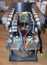
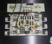
This is front end board. It's mounted to rear panel by the FETs. The 3 pots for bias and offset are mounted to the board from behind (the board is double sided). There are holes in the rear panel to adjust those pots, so all ajustments can be done without opening an amp. The small board mounts directly to the input jacks (Balanced and RCA) and from here with resistors and wire the signal goes directly to the main board. This way I avoided wiring completely. There are only 2 short wires to the output stage and that's all. Again, this was A75.
Attachments

Here's a tuning trick to try, peel off the plastic shrink on the AC Filter caps in your power supplies. Get yourself several yards of solid core 20 to 26 AWG wire and tightly wrap the exposed caps covering as much of the can as you can, (pun intended). Do this for all your caps connect the open ends at the top and bottoms of the coils to form a long chain. connect one to Chassis Ground close to the caps and the other to the ground rail between the caps. You can epoxy the coils in place or try soldering in a few spots. I suggest Epoxy and a bead of Stabilant 22A drizzled along the coils.
Anthony
Anthony
I'm not that much of a fanatic yet
I beg to differ the evidence says otherwise.
Actually it helps reduce the HF noise emitted from the cans due to the properties of electron flow throw dielectric.
Anthony
For an amp like this my choice goes to P2P. Look at Jonathan Carr's preamp: http://www.connoisseurdefinitions.com/model_3.htm
It's nothing short of an art form, not to mention that p2p sounds superior.
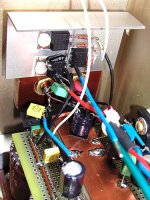
I got everything done except the front end board. I'll use a piece of aluminum and mount everything there using aluminum as a heat sink for FETs. The circuit is simple enough not to bother with PCB. You see how simple it looks in my Aleph5.
It's nothing short of an art form, not to mention that p2p sounds superior.
I got everything done except the front end board. I'll use a piece of aluminum and mount everything there using aluminum as a heat sink for FETs. The circuit is simple enough not to bother with PCB. You see how simple it looks in my Aleph5.
Attachments
I'm like Jocko, I don't make schematics. I use whatever was posted in Aleph X thread and basic Aleph 2 schematic, and go on. As I said, I only have the front end board left, to finish the amp. I'm not really rushing now, because the journey is more exciting than the end itself.
I use whatever was posted in Aleph X thread and basic Aleph 2 schematic, and go on. As I said, I only have the front end board left, to finish the amp. I'm not really rushing now, because the journey is more exciting than the end itself.- Status
- This old topic is closed. If you want to reopen this topic, contact a moderator using the "Report Post" button.
- Home
- Amplifiers
- Pass Labs
- This is not just another Aleph