It's been explained here http://www.diyaudio.com/forums/showthread.php?s=&threadid=3894&highlight=snubbers
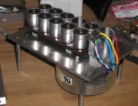
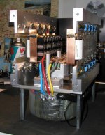
And here's how the bridges are mounted and connected with the rest. The capacitors are Black Gates (as seen in the other thread") ). This is the smaller bank, two other banks will be installed next to output devices with thermistors in between. Two standoffs on top will be used to mount front end board.
). This is the smaller bank, two other banks will be installed next to output devices with thermistors in between. Two standoffs on top will be used to mount front end board.
I always like to use as shortest connections as posible, so you might notice that the bridge is in direct path between transformer and caps. The 1/4" aluminum platform is not only base that supports everything, but also a shield between AC input circuits (not installed yet) and tranformer and the rest of the amp.
). This is the smaller bank, two other banks will be installed next to output devices with thermistors in between. Two standoffs on top will be used to mount front end board.I always like to use as shortest connections as posible, so you might notice that the bridge is in direct path between transformer and caps. The 1/4" aluminum platform is not only base that supports everything, but also a shield between AC input circuits (not installed yet) and tranformer and the rest of the amp.
Attachments

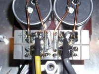
I'll be using 2 paralleled CL-60 per rail. I don't know how it'll turn out thou. Star ground is at the bridge.
http://www.thermometrics.com/assets/images/cl.pdf
http://www.thermometrics.com/assets/images/cl.pdf
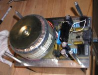
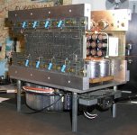
Here's the other side of my PS module. Transformer is 750VA, with primaries in series to reduce the secondary voltage. I'm getting +/- 22 v DC without load now. The schematic for the AC input filtering and switching is here: http://www.diyaudio.com/forums/showthread.php?s=&threadid=3924&highlight=schematic+explanation
I'm using a circuit to eliminate DC component from AC line. It's taken from ML 23.5. Indeed, when I was using it in A75, the tranformers were extremally quiet without a smallest hum. The power is switched through a triac by a togle switch and remotedly by wire using 12V relay. I used two CL-70 thermistors connected in series for inrush protection. It may be overkill, but I'm tired of changing bridges.
Transformer is mounted using a damping sheet for isolation from the rest of the chassis. The four standoffs are used to mount bottom panel as well as amp's feet.
I'm running a bit late, I thought it would be done this week, but it looks more like a next one.
Attachments

peter daniel
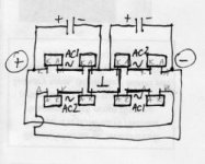
recently you asked about how to derive a split supply from a transformer without a center tap. draw two bridges with there primaries in parallel,the top bridge take of the pos as normal, the neg of top bridge connect to the pos of the lower bridge this will be ground. the neg of the lower bridge will be negative out.if this is not clear I will buy a cable for my scanner
recently you asked about how to derive a split supply from a transformer without a center tap. draw two bridges with there primaries in parallel,the top bridge take of the pos as normal, the neg of top bridge connect to the pos of the lower bridge this will be ground. the neg of the lower bridge will be negative out.if this is not clear I will buy a cable for my scanner
Banned
Joined 2002
If you check my profile, it says "full time DIY".
My background is in mechanical engineering thou, and my studies were concentrated on marine power plants. I didn't like too much, and electronics was always drawing my full time attention.
Last decade I spent working on aircrafts (mods, maintenance, production) and I kind of liked it. Whenever I have free time I like to design and built stereo equipment. While working on aircrafts my specialty is sheet metal and aircraft structure, so aluminum doesn't present much mystery to me and I can easily shape it to desired form.
But it's not only about that. For me the biggest challenge is to put it together into a nice functional form, with maximum simplicity, yet complicated enough to provide the purest signal path and minimum connections. And that's were the fun beginns.
Banned
Joined 2002

The output modules are added, the only thing left to be done is front end board. It will be mounted on the two standoffs between capacitor banks. I also have to run wires from the bridge to the output devices. The flat pieces of copper is actually Goertz speaker wire. I like to use it for high current applications and here it makes the output bus. It connects rom here with single Caddock 0.1 ohm resistors to binding posts.
Attachments
That's the side view. The chassis is self supporting and does not depend on panels to hold it together. This is quite convenient and in case of troubleshooting, I can easily remove heatsinks and if necessary, change the output devices. The 4 holes in the transistors bars hold the back panel, the same for the front panel. Four more screws on top for the top panel, the bottom panel and feet are attached to the standoffs. The heatsinks are attached with 8 screws on ea. side.
Attachments
- Status
- This old topic is closed. If you want to reopen this topic, contact a moderator using the "Report Post" button.
- Home
- Amplifiers
- Pass Labs
- This is not just another Aleph