Bypass caps- No
Well mac, to describe what I said as "bunk" is fundamentally rude and disrespectful. I have no problem that you disagree...
Additionally to interpret what I said as advocating high power supply impedance misrepresents my position. If you want some actual scientific proof that simple bypassing promotes high frequency resonance (as opposed to quoting a statement from Mr Borbely) then there is a thread on this site where a member measures and posts the effects of bypassing. I recall it was a thread on power supply "snubbers". You will be able to find it if you search, let me know if you can't.
What I advocate is using a zobel or "snubber" to minimise the negative effects of bypassing. And BTW the resonant tank circuit created when bypassing power supply capacitors is a very well known and reported phenomenon. Whether it affects sound quality negatively is open to debate, I have made my experiences known for what they are worth.
BTW, bypassing the caps in a Hypex class D amp may be OK, the module has a "snubber" in the form of a high esr electrolytic on board. This may damp resonant effects in the bypassed bulk storage capacitors.
Rob.
Re: Bypass caps- No
Sorry, no disrespect intended.
I'm aware of the counter argument but don't find it compelling. Using bypass caps is one $12 tweak that's easily reversible. I recommend at least trying it. YMMV
Robert F said:Well mac, to describe what I said as "bunk" is fundamentally rude and disrespectful. I have no problem that you disagree...
Sorry, no disrespect intended.
I'm aware of the counter argument but don't find it compelling. Using bypass caps is one $12 tweak that's easily reversible. I recommend at least trying it. YMMV
Bypass caps- No
Tom,
I have no wish to make more of this than it deserves, but I prefaced the remark you quoted with "IME" which means "in my experience". Tell me why this is "overconfident" since it relates my actual experience? Every time I have tried simple bypassing I have not liked the result...
I am happy with mac's gracious apology, I am sure that much of what people take umbrage with in these internet discussion groups is unintentional.
Rob.
with every additional post i read, i get farther and farther away from my goal of building my amp
Hey, you have a lot of stuff laying around, why not just build the amp with what you got already? Build it and enjoy it, tweak later.
There's a zillion factors that will define the sound of your amps but it's only details...
I went from a cheapo old little transformer with 2 of those "cheesy" caps and a $1 block rectifier on them to the 500VA/HG hypex solution. I never compared the solutions side by side, but it sounds very much the same, just more control in the bass, but that's just due to more clean amps available, not some cap-voodoo.
I think that the PS is less important in class-d (as long as it is beefy enough) due to the way the class-d works. I'm going to make a weird anology now... lol
")
If electricity was running water, I imagine a normal amp as 2 faucets controlling the running water into the speakers, so to say. It's important that the water reaches the faucet very cleanly, because what comes out of the faucet is exactly what we are going to hear.
Now a class-D faucet
- it's different: now we're talking water injectors that blast water out at full power or nothing at all - beneath this there is a "pool" (=output cap circuitry) of water that streams through an opening at a speed depending on the amount of water in the pool.in case 1 the streaming of the water is defined by the faucet, in case 2 it's the pool.
As long as the water can be pushed through the water injectors fast enough (=enough current available) - the pools work like they should.
An in fact, when I replaced older v1.1 modules by those released in november there was a slight difference in sound, not better or worse but different - checked the modules, completely different type of output cap present.
That's only my weird view on it, but they taught me to "think outside the box"

Re: Re: Bypass caps- No
Hi,
Robert, you really seem to know your stuff.
Whereas in your reply Mac.... and I mean no offence by this just trying to help people out here as I see the cloud of confusion roll in:
"Low ESR means low impedance at high frequencies. "
You couldn't be more wrong.
ESR is "resistance" and impedance is another matter.
ESR will stay the same across all frequencies, it's a constant in the equation. The impedance, brought on by the ESL which causes inductive "reactance" along with the constant of ESR is actually what forms the total impedance. So, ESL is in fact what causes the impedance to rise at high frequency, it's why the response graphs takes on the appearance of a checkmark that rises with frequency.
Buying good audio grade caps is a way of attaining low ESL, maybe, but not the answer for it. There's other reasons for high grade audio caps, they can be constructed rather differently using a variety of materials and techniques (black gates, cerafines, four poles, slit foils.... ) in attempts to address "other" issues normally gone ignored. They still have ESL. BHC T networks are probaby the best money can ever buy combining the T-network technology with slit foil.
The more caps you parallel , the higher capacitance you get (good stuff) the lower ESR goes (good stuff too), the higher ESL goes (bad stuff, the less linear the response).
You'll note on the TNT PSU design article they made a quick mention of ESL. Simply saying "ignore it for now". They ignored it later too, but should you?
As Robert said, you can counter ESL by way of snubbers, which essentially operate on the same principles as a Zobel network.
A "snubber" is actually the correct use of the term, Zobel being restricted to the use of speaker response correction, not that of the supply. A snubber is also a general term used for all kinds of little "correction" networks ranging from the simple to the very complex and with all kinds of different things which they correct for. It makes it alot of fun to research, this is where the hint of it working like a zobel is useful for you.
You might be able to get away with throwing given values in, you may also consider that a band aid. Correctly used the snubber does exactly as stated, and counters ESL. That means it must be measured, specific to application.
Yes the UCD modules do have snubbers on board. You may rely on them to counter the ESL of the traces and of the onboard bypass/local filter caps. They can't guarantee to correct for the kind of ESL that 100 caps in // or the kind/length of wire you use might have.
Experimentation is good, research is good too. For best results, do some homework and get your hands dirty. This isn't as lego like as it may first appear. I "plugged" this amp in in the very worst possible way when I first got it so I could experience how it sounded like I thought the majority would use it. It does not dissapoint. Since I've taken it to a new level, is it worth it? Does it respond to better implemenation? HELL YEAH.
I've been lucky enough with the use of Jensen 4 poles that ESL doesn't "sound" like it's a problem for me, not having the equipment to measure, I'm not going to bother with snubbers, but I know if I did it could be pushed even further.
Simply throwing a "poly" in // with the electrolytics is not a snubber, and "will" cause resonance. Your goal shouldnt' be to mess with the filters Q by creating a resonant tank circuit, it should simply be to tweak the Q of the filter. (filter being the PSU caps).
I look forward to more of your posts Rob.
Cheers,
Chris
mac said:
IMO this is complete bunk. In essense you advocating the use of high-ESR caps in the power supply. I don't think many will agree with you on that point.
Low ESR means low impedance at high frequencies. Using poly caps to bypass standard electrolytic caps in a power supply has the same effect as using expensive, specially formulated low-ESR filter caps like Black Gates.
But don't take my word for it. Erno Borbely knows a thing or two about amplifier power supply design. From his website:
"Electrolytics are usually specified with ESR (Equivalent Series Resistance). It is important to use caps with low ESR. For low and medium power applications we are using ELNA CERAFINE and Nichicon caps, which have been designed for high performance audio, or ROE/Frolyt caps, which have been designed for switch-mode power supplies. The Panasonic FC electrolytics are also very much used in this power range. The electrolytic caps show increasing impedance at high frequencies (usually above 10kHz), so it is a good practice to parallel the electrolytic with film caps."
http://www.borbelyaudio.com/power_supplies.asp
I've had good success using Solen Fast Caps in my UcD power supplies. They aren't too expensive and are of good quality.
Hi,
Robert, you really seem to know your stuff.
Whereas in your reply Mac.... and I mean no offence by this just trying to help people out here as I see the cloud of confusion roll in:
"Low ESR means low impedance at high frequencies. "
You couldn't be more wrong.
ESR is "resistance" and impedance is another matter.
ESR will stay the same across all frequencies, it's a constant in the equation. The impedance, brought on by the ESL which causes inductive "reactance" along with the constant of ESR is actually what forms the total impedance. So, ESL is in fact what causes the impedance to rise at high frequency, it's why the response graphs takes on the appearance of a checkmark that rises with frequency.
Buying good audio grade caps is a way of attaining low ESL, maybe, but not the answer for it. There's other reasons for high grade audio caps, they can be constructed rather differently using a variety of materials and techniques (black gates, cerafines, four poles, slit foils.... ) in attempts to address "other" issues normally gone ignored. They still have ESL. BHC T networks are probaby the best money can ever buy combining the T-network technology with slit foil.
The more caps you parallel , the higher capacitance you get (good stuff) the lower ESR goes (good stuff too), the higher ESL goes (bad stuff, the less linear the response).
You'll note on the TNT PSU design article they made a quick mention of ESL. Simply saying "ignore it for now". They ignored it later too, but should you?
As Robert said, you can counter ESL by way of snubbers, which essentially operate on the same principles as a Zobel network.
A "snubber" is actually the correct use of the term, Zobel being restricted to the use of speaker response correction, not that of the supply. A snubber is also a general term used for all kinds of little "correction" networks ranging from the simple to the very complex and with all kinds of different things which they correct for. It makes it alot of fun to research, this is where the hint of it working like a zobel is useful for you.
You might be able to get away with throwing given values in, you may also consider that a band aid. Correctly used the snubber does exactly as stated, and counters ESL. That means it must be measured, specific to application.
Yes the UCD modules do have snubbers on board. You may rely on them to counter the ESL of the traces and of the onboard bypass/local filter caps. They can't guarantee to correct for the kind of ESL that 100 caps in // or the kind/length of wire you use might have.
Experimentation is good, research is good too. For best results, do some homework and get your hands dirty. This isn't as lego like as it may first appear. I "plugged" this amp in in the very worst possible way when I first got it so I could experience how it sounded like I thought the majority would use it. It does not dissapoint. Since I've taken it to a new level, is it worth it? Does it respond to better implemenation? HELL YEAH.
I've been lucky enough with the use of Jensen 4 poles that ESL doesn't "sound" like it's a problem for me, not having the equipment to measure, I'm not going to bother with snubbers, but I know if I did it could be pushed even further.
Simply throwing a "poly" in // with the electrolytics is not a snubber, and "will" cause resonance. Your goal shouldnt' be to mess with the filters Q by creating a resonant tank circuit, it should simply be to tweak the Q of the filter. (filter being the PSU caps).
I look forward to more of your posts Rob.
Cheers,
Chris
There's "P" in your "ool"
I think to add to your analogy would be that ESL equates to the viscocity of the water, thickening it at higher frequencies, while ESR might equate to the pipe diameter.
You would think it perhaps even more crucial to have this as optimal as possible considering some freak is playing with your tap by turning it on and off ~half a milion times a second.
How long are you willing to wait to fill your pot of coffee?
If the water is so thick that it can hardly begin to flow by the time the tap is cut off again, you'll never get your pot filled will you?
The fact remains that the caps are still in the direct path of the signal, so is the transformer, so is your power cord, and that's why it all matters.
BTW I'm not saying you need a golden magic shielded to the outlet power cable, but a proper gauge at least, and shielding has it's place inside the case.
People need to realize that "audio grade" caps aren't a cure all. They're also not a gimmick. Some are though, I don't know what makes nichicon gold/audio series different than any other industrial cap, other than the gold plated lugs, which is unimportant after you make your oxygen free connection.
If you dont' attend to the bio-chemic needs of your pool the algea takes over and you're left with a green slop.
Makes ya think I guess anyway.
Cheers,
Chris
Yves Smolders said:
Hey, you have a lot of stuff laying around, why not just build the amp with what you got already? Build it and enjoy it, tweak later.
There's a zillion factors that will define the sound of your amps but it's only details...
I went from a cheapo old little transformer with 2 of those "cheesy" caps and a $1 block rectifier on them to the 500VA/HG hypex solution. I never compared the solutions side by side, but it sounds very much the same, just more control in the bass, but that's just due to more clean amps available, not some cap-voodoo.
I think that the PS is less important in class-d (as long as it is beefy enough) due to the way the class-d works. I'm going to make a weird anology now... lol
If electricity was running water, I imagine a normal amp as 2 faucets controlling the running water into the speakers, so to say. It's important that the water reaches the faucet very cleanly, because what comes out of the faucet is exactly what we are going to hear.
Now a class-D faucet
in case 1 the streaming of the water is defined by the faucet, in case 2 it's the pool.
As long as the water can be pushed through the water injectors fast enough (=enough current available) - the pools work like they should.
An in fact, when I replaced older v1.1 modules by those released in november there was a slight difference in sound, not better or worse but different - checked the modules, completely different type of output cap present.
That's only my weird view on it, but they taught me to "think outside the box"
I think to add to your analogy would be that ESL equates to the viscocity of the water, thickening it at higher frequencies, while ESR might equate to the pipe diameter.
You would think it perhaps even more crucial to have this as optimal as possible considering some freak is playing with your tap by turning it on and off ~half a milion times a second.
How long are you willing to wait to fill your pot of coffee?
If the water is so thick that it can hardly begin to flow by the time the tap is cut off again, you'll never get your pot filled will you?
The fact remains that the caps are still in the direct path of the signal, so is the transformer, so is your power cord, and that's why it all matters.
BTW I'm not saying you need a golden magic shielded to the outlet power cable, but a proper gauge at least, and shielding has it's place inside the case.
People need to realize that "audio grade" caps aren't a cure all. They're also not a gimmick. Some are though, I don't know what makes nichicon gold/audio series different than any other industrial cap, other than the gold plated lugs, which is unimportant after you make your oxygen free connection.
If you dont' attend to the bio-chemic needs of your pool the algea takes over and you're left with a green slop.
Makes ya think I guess anyway.
Cheers,
Chris
Re: Bypass caps- No
For what it is worth, I fully agree here. I have actually done several measurements on CAPS as well. What I do is I use a square wave generator and connect that to a RC network (R=100 Ohm most of the time) and the C is the cap that I'm testing. I measure the voltage over the CAP using a scope. The frequency of the square wave should be high enough so that the voltage over the cap is small in comparison to the square wave voltage. Doing this, I essentially put a square wave current in the CAP and can see the ESR and other effects of the CAP. What you can see very nicely is that BG caps have a low ESR (low voltage jump when the current switches) and that bypassing the BG with a 100n film cap gives you a very nice resonant circuit that you for sure not want to have. A snubber would be needed to get rid of that resonance. I will see if I can find back some of my measurement data to show it.
Best regards
Gertjan
Robert F said:Well mac, to describe what I said as "bunk" is fundamentally rude and disrespectful. I have no problem that you disagree...
Additionally to interpret what I said as advocating high power supply impedance misrepresents my position. If you want some actual scientific proof that simple bypassing promotes high frequency resonance (as opposed to quoting a statement from Mr Borbely) then there is a thread on this site where a member measures and posts the effects of bypassing. I recall it was a thread on power supply "snubbers". You will be able to find it if you search, let me know if you can't.
What I advocate is using a zobel or "snubber" to minimise the negative effects of bypassing. And BTW the resonant tank circuit created when bypassing power supply capacitors is a very well known and reported phenomenon. Whether it affects sound quality negatively is open to debate, I have made my experiences known for what they are worth.
BTW, bypassing the caps in a Hypex class D amp may be OK, the module has a "snubber" in the form of a high esr electrolytic on board. This may damp resonant effects in the bypassed bulk storage capacitors.
Rob.
For what it is worth, I fully agree here. I have actually done several measurements on CAPS as well. What I do is I use a square wave generator and connect that to a RC network (R=100 Ohm most of the time) and the C is the cap that I'm testing. I measure the voltage over the CAP using a scope. The frequency of the square wave should be high enough so that the voltage over the cap is small in comparison to the square wave voltage. Doing this, I essentially put a square wave current in the CAP and can see the ESR and other effects of the CAP. What you can see very nicely is that BG caps have a low ESR (low voltage jump when the current switches) and that bypassing the BG with a 100n film cap gives you a very nice resonant circuit that you for sure not want to have. A snubber would be needed to get rid of that resonance. I will see if I can find back some of my measurement data to show it.
Best regards
Gertjan
Some are though, I don't know what makes nichicon gold/audio series different than any other industrial cap, other than the gold plated lugs, which is unimportant after you make your oxygen free connection.
Well, if you ask Nichicon they'll tell you!
Like most 'audio grade' caps it's down to internal materials, electrolytes and foil magnification factors.
Doesn't mean they sound any good though - *some* of the Muse series are the worst caps I've ever heard!
Andy.
Re: Re: Re: Bypass caps- No
If you have ever seen a datasheet for a capacitor you would have noted that ESR is always plotted against frequency. If my statement were wrong the plot would be a straight line. Here is what ESR looks like for a Blaqck Gate N:
Definition of ESR: ESR is the sum of in-phase AC resistance. It includes resistance of the dielectric, plate material, electrolytic solution, and terminal leads at a particular frequency. ESR acts like a resistor in series with a capacitor (thus the name Equivalent Series Resistance). This resister can cause circuits to fail that look just fine on paper and is often the failure mode of capacitors.
To charge the dielectric material current needs to flow down the leads, through the lead plate junction, through the plates themselves - and even through the dielectric material. The dielectric losses can be thought of as friction of aligning dipoles and thus appear as an increase of measured ESR as frequency increases.
Now, if you're arguing semantics with me, that's another thing. While ESR is technically just the resistive portion of the inductive impedance of a capacitor, it's common to refer to the whole as ESR.
Given this, I call into question your motivation for coming across as a horse's rear quarter.
classd4sure said:
"Low ESR means low impedance at high frequencies. "
You couldn't be more wrong.
ESR is "resistance" and impedance is another matter.
ESR will stay the same across all frequencies, it's a constant in the equation.
If you have ever seen a datasheet for a capacitor you would have noted that ESR is always plotted against frequency. If my statement were wrong the plot would be a straight line. Here is what ESR looks like for a Blaqck Gate N:
An externally hosted image should be here but it was not working when we last tested it.
Definition of ESR: ESR is the sum of in-phase AC resistance. It includes resistance of the dielectric, plate material, electrolytic solution, and terminal leads at a particular frequency. ESR acts like a resistor in series with a capacitor (thus the name Equivalent Series Resistance). This resister can cause circuits to fail that look just fine on paper and is often the failure mode of capacitors.
To charge the dielectric material current needs to flow down the leads, through the lead plate junction, through the plates themselves - and even through the dielectric material. The dielectric losses can be thought of as friction of aligning dipoles and thus appear as an increase of measured ESR as frequency increases.
Now, if you're arguing semantics with me, that's another thing. While ESR is technically just the resistive portion of the inductive impedance of a capacitor, it's common to refer to the whole as ESR.
Given this, I call into question your motivation for coming across as a horse's rear quarter.
Re: Re: Re: Re: Bypass caps- No
Dearest Mac,
If my saying "you're wrong" makes you think ill of me, then, I guess, allow me to reaffirm your position.
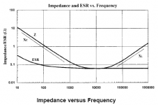
I'll first say that wasn't the best graph to make your point with. Looks like more of an add to me, but you brought it to the table, so we may as well have a look at it. It looks to me like what they're showing on the Y axis is "impedance" and not ESR. I fail to see how that can be arguing symantics when it's the whole poit of this discussion-what snubbers compensate for-what's actually responsible for the rise in the response curve?
You're arguing it's ESR, I said ESL. So there's no symantics there.
Actually, it say's "Impedance. E.R.S". Can you tell me what ERS is? It doesn't appear in the legend? To me, it would appear as a marketing add for their caps wired in "super E" configuration, and so dont' mind me if I choose to dismiss the technical validity of it, especially when they fail to label the axis appropriatly, from what I can see.
Maybe I was wrong about something, I did say ESR was constant across all frequencies..... guess I over simplified things. So we'll agree it varies with frequency. Let's then look at how, shall we?
Excerpt from some Cornel Dubilier paper:
"...at low frequencies the
ESR declines steadily with increasing frequency and crosses
over to constant ESR at a frequency inversely proportional
to capacitance. This crossover is typically below 10
kHz. The ESR of high-capacitance capacitors changes little
with increasing frequency because high-capacitance causes
them to have low crossover frequencies."
Now, the changes in the dielectric you quoted are said to increase ESR with frequency, that doesn't mean that the curve rises, it just falls less rapidly (levels off). So as I said already, what you're seeing when the impedance curve rises is the ESL which is what snubbers compensate for.
Now for a graph that's a bit less of an add, and perhaps a little bit more scientific, from that very same paper.
:FIM:
Regards,
"ain't ivur seen a detuh cheet befure..."
Chris
mac said:
If you have ever seen a datasheet for a capacitor you would have noted that ESR is always plotted against frequency. If my statement were wrong the plot would be a straight line. Here is what ESR looks like for a Blaqck Gate N:
An externally hosted image should be here but it was not working when we last tested it.
Definition of ESR: ESR is the sum of in-phase AC resistance. It includes resistance of the dielectric, plate material, electrolytic solution, and terminal leads at a particular frequency. ESR acts like a resistor in series with a capacitor (thus the name Equivalent Series Resistance). This resister can cause circuits to fail that look just fine on paper and is often the failure mode of capacitors.
To charge the dielectric material current needs to flow down the leads, through the lead plate junction, through the plates themselves - and even through the dielectric material. The dielectric losses can be thought of as friction of aligning dipoles and thus appear as an increase of measured ESR as frequency increases.
Now, if you're arguing semantics with me, that's another thing. While ESR is technically just the resistive portion of the inductive impedance of a capacitor, it's common to refer to the whole as ESR.
Given this, I call into question your motivation for coming across as a horse's rear quarter.
Dearest Mac,
If my saying "you're wrong" makes you think ill of me, then, I guess, allow me to reaffirm your position.
I'll first say that wasn't the best graph to make your point with. Looks like more of an add to me, but you brought it to the table, so we may as well have a look at it. It looks to me like what they're showing on the Y axis is "impedance" and not ESR. I fail to see how that can be arguing symantics when it's the whole poit of this discussion-what snubbers compensate for-what's actually responsible for the rise in the response curve?
You're arguing it's ESR, I said ESL. So there's no symantics there.
Actually, it say's "Impedance. E.R.S". Can you tell me what ERS is? It doesn't appear in the legend? To me, it would appear as a marketing add for their caps wired in "super E" configuration, and so dont' mind me if I choose to dismiss the technical validity of it, especially when they fail to label the axis appropriatly, from what I can see.
Maybe I was wrong about something, I did say ESR was constant across all frequencies..... guess I over simplified things. So we'll agree it varies with frequency. Let's then look at how, shall we?
Excerpt from some Cornel Dubilier paper:
"...at low frequencies the
ESR declines steadily with increasing frequency and crosses
over to constant ESR at a frequency inversely proportional
to capacitance. This crossover is typically below 10
kHz. The ESR of high-capacitance capacitors changes little
with increasing frequency because high-capacitance causes
them to have low crossover frequencies."
Now, the changes in the dielectric you quoted are said to increase ESR with frequency, that doesn't mean that the curve rises, it just falls less rapidly (levels off). So as I said already, what you're seeing when the impedance curve rises is the ESL which is what snubbers compensate for.
Now for a graph that's a bit less of an add, and perhaps a little bit more scientific, from that very same paper.
:FIM:
Regards,
"ain't ivur seen a detuh cheet befure..."
Chris
Attachments
mac said:
If you have ever seen a datasheet for a capacitor you would have noted that ESR is always plotted against frequency. If my statement were wrong the plot would be a straight line. Here is what ESR looks like for a Blaqck Gate N:
An externally hosted image should be here but it was not working when we last tested it.
Definition of ESR: ESR is the sum of in-phase AC resistance. It includes resistance of the dielectric, plate material, electrolytic solution, and terminal leads at a particular frequency. ESR acts like a resistor in series with a capacitor (thus the name Equivalent Series Resistance). This resister can cause circuits to fail that look just fine on paper and is often the failure mode of capacitors.
To charge the dielectric material current needs to flow down the leads, through the lead plate junction, through the plates themselves - and even through the dielectric material. The dielectric losses can be thought of as friction of aligning dipoles and thus appear as an increase of measured ESR as frequency increases.
Now, if you're arguing semantics with me, that's another thing. While ESR is technically just the resistive portion of the inductive impedance of a capacitor, it's common to refer to the whole as ESR.
Given this, I call into question your motivation for coming across as a horse's rear quarter.
Dearest Mac,
If my saying "you're wrong" makes you think ill of me, then, I guess, allow me to reaffirm your position.
I'll first say that wasn't the best graph to make your point with. Looks like more of an add to me, but you brought it to the table, so we may as well have a look at it.
It looks to me like what they're showing on the Y axis is "impedance" and not ESR. I fail to see how that can be arguing semantics when it's the whole point of this discussion-what snubbers compensate for-what's actually responsible for the rise in the response curve-non linear response "at high frequency" as you said?
You're arguing it's ESR, I said ESL. So there's no semantics there, is there?
Actually, it say's "Impedance. E.R.S" on the axis. Can you tell me what ERS is? It doesn't appear in the legend? Where does it even show ESR Vs ESL? Poor choice indeed.
Maybe I was wrong about something, I did say ESR was constant across all frequencies..... guess I over simplified things. So we'll agree it varies with frequency. Let's then look at how, shall we?
Excerpt from some Cornel Dubilier paper:
"...at low frequencies the
ESR declines steadily with increasing frequency and crosses
over to constant ESR at a frequency inversely proportional
to capacitance. This crossover is typically below 10
kHz. The ESR of high-capacitance capacitors changes little
with increasing frequency because high-capacitance causes
them to have low crossover frequencies."
Now, the changes in the dielectric you quoted are said to increase ESR with frequency, that doesn't mean that the curve rises, it just falls less rapidly (levels off). So as I said already, what you're seeing when the impedance curve rises is the ESL which is what snubbers compensate for.
Now for a graph that's a bit less of an add, and perhaps a little bit more scientific, from that very same paper.
C'mon Mac, do some real homework, or don't be so quick to dismiss that of those who do

Regards,
"ain't ivur seen a detuh cheet befure..."
Chris
Attachments

classd4sure said:Maybe I was wrong about something, I did say ESR was constant across all frequencies..... guess I over simplified things. So we'll agree it varies with frequency.
Yes Chris, you were wrong.
For the benefit of others I have updated the graph to better illustrate my point that ESR does in fact vary with frequency. The graph now shown was randomly pulled from a CDE datasheet.
An externally hosted image should be here but it was not working when we last tested it.
mac said:
Yes Chris, you were wrong.
For the benefit of others I have updated the graph to better illustrate my point that ESR does in fact vary with frequency. The graph now shown was randomly pulled from a CDE datasheet.
An externally hosted image should be here but it was not working when we last tested it.
Whatever you say mac. I'm glad you've taken my hint to research some CDE papers and gotten away form the marketting adds.
It however illustrates my point, and not yours. Unless I'm blind? Maybe you can edit that and show me where ESR is "rising" with frequency as you said it does.

Bypass caps- No
I see there has been a little "action" since I last logged on here
I think we could usefully discuss at this point how to make a better sounding amp using the ideas Chris and I (and others) have discussed.
A useful starting point is to examine the amp/ power supply as a system. I think of the average power amp and power supply as chaos in action:
With your average class A/B amp we have a capacitor input power supply which draws serious pulsed current from the transformer as the rectifier diodes switch. This pulsed current interacts with the leakage inductance of the power transformer
which rings and creates noise with harmonics which extend into the Mhz. This noise rides along with the rectified DC feeding your amplifier.
Now factor in here that the amplifier with music playing is drawing current which varies with the signal. This modulates the already noisy power supply in time with the music. Now think about it, what happens if our bulk power supply has a substantial
resonance resulting from an undamped tank circuit as a result of bypassing with a polypropylene capacitor? This resonance will be excited in an unpredictable fashion which may depend at least partially on the music program being played.
Now if we build our power amp in the way many people do; with untwisted power supply wiring, signal leads in close proximity to the P.S. leads etc, then we have a nice rf generator which bleeds into the signal path. Add to this the fact that the amplifier will have poor power supply rejection at rf frequencies...
So, is this a problem subjectively and if so what can we do about it? That can wait for another post.
Rob.
Bypass caps- No
I note I left something important out of my last post. The LC tank circuit excited by the rectifiers switching is formed by the leakage inductance of the transfomer and the junction capacitance of the rectifier diodes.
In order to control some of the chaos earlier referred to, we can use a snubber on the secondary of the power transformer or accross the rectifier diodes. Ideally the value of the snubber will be derived individually for each transformer/rectifier combo. However with the UCD 180 I built for my brother in law I simply used hexfreds, twisted the secondary wiring of the transfomer, made the rectifier to filter cap wiring as short as possible and left it at that. It sounds very good.
For my current amp project (a zero overall feed back class A/B amp) I will be a bit more particular since it is for me and I can play a bit more without the time constraints.
Rob.
Bypass caps -- Yes
I bypass with teflon capacitors. Every power supply I've bypassed, which is every power supply in my audio video system, sounds/looks better to my ears/eyes (video improvements are easy to spot). The tank resonance created by my prodigious bypassing must cause less trouble than the bypassing solves, which is not so difficult to understand given electrolytics are the absolute bottom feeders of electrical components. I don't see a consensus yet on this issue, Rob.
I bypass with teflon capacitors. Every power supply I've bypassed, which is every power supply in my audio video system, sounds/looks better to my ears/eyes (video improvements are easy to spot). The tank resonance created by my prodigious bypassing must cause less trouble than the bypassing solves, which is not so difficult to understand given electrolytics are the absolute bottom feeders of electrical components. I don't see a consensus yet on this issue, Rob.
Bypass caps- No
Hi Tom,
I am quite happy for there not to be a consensus, with subjective listening I would be surprised if we ever reached that point on anything. Still... what would happen if you added a snubber and damped the tank cct caused by your teflon bypasses? Maybe an even greater improvement?
My very subjective observations on simple bypassing (not with teflons btw) is that the results are very program dependant; on some music I can be impressed, but they don't do it accross a range of music and make some things sound worse. More to the point they seem to reduce the sonic differences between recordings, imposing a spotlit quality on everything and they make the system subjectively noisier. YMMV and obviously does.
Rob
- Status
- This old topic is closed. If you want to reopen this topic, contact a moderator using the "Report Post" button.
- Home
- Amplifiers
- Class D
- thinking about the UCD modules.