Agreed and hence the "FWIW" and why I want to test the 2SC6144SG for stability. I think I will leave the min-fT-of-650MHz MMBTH10 in place versus the 100MHz-700MHz fT MMBT6429 - perhaps my batch of the latter has fT at the lower end of the range.
Previously I rather superficially tried to superimpose an AC waveform at the input of the Sziklai predecessor to this regulator. I merely coupled my signal generator to the same place I had connected the DC input from my bench supply. My Rigol DG1022 signal generator was having nothing to do with it. Perhaps I need to couple the AC in via a cap. I haven't given it much thought since that one, brief attempt. I was also deterred somewhat by the realisation when trying to measure the noise of my Self's Balanced Input Board with my Samuel Groner measurement amplifier that one really has to go to great lengths to shield the DUT and measurement amplifier cabling.
Previously I rather superficially tried to superimpose an AC waveform at the input of the Sziklai predecessor to this regulator. I merely coupled my signal generator to the same place I had connected the DC input from my bench supply. My Rigol DG1022 signal generator was having nothing to do with it. Perhaps I need to couple the AC in via a cap. I haven't given it much thought since that one, brief attempt. I was also deterred somewhat by the realisation when trying to measure the noise of my Self's Balanced Input Board with my Samuel Groner measurement amplifier that one really has to go to great lengths to shield the DUT and measurement amplifier cabling.
Last edited:
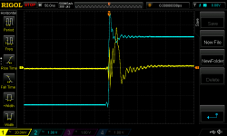

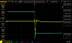
Am I right to see the ringing as circa 80 MHz well above the modelled unity gain frequency which is more like 1.5MHz? Hence it is likely ringing from parasitics, perhaps because I have no base stopper? It would seem, however, that having to use such a stopper is likely to kill off a good deal of any advantage that might be had from a higher fT pass transistor.
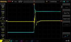
But I think you are right (as usual). I just powered it all up and took the (second two) measurements again (plus a look at 10mV per division, 32 sample averaging). Much less scary today.
Attachments
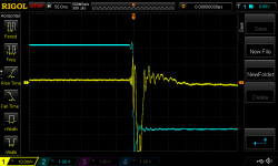
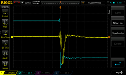
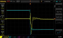
The good news is, the entire assembly is stable / non oscillatory, as it exists today, even with the imperfect transient response of the preregulator. If/when you tweak the RC network on the preregulator output to improve its load regulation, this will only improve the final result.
BTW I read that Walt Jung article linked in post #320, and found out how he measured 120dB line rejection. It's scary. 1V input, 1 microvolt output, measured with an Audio Precision system 2 rig ($40K?). I don't have any idea whether such is possible using PC soundcards and homebuilt preamps and software ... but it seems daunting.
And Walt requires you to remove all input capacitors from the raw DC supply terminal of your voltage regulator board (his 200kHz rail driver has to drive those caps!), and replace them all with a single 0.1uF capacitor. The impedance of 0.1uF at 200kHz is 8 ohms, so his raildriver pumps out (1v / 8R) = 0.125 amps at 200 kHz. I now see why he won't let you connect 220uF to his rail driver!
Indeed. Many thanks for your considerable assistance.
I think with proper shielding I can measure below 120dBV with Sam Groner's preamp and ARTA, although obviously not so high in frequency (the sound card I would use is capped at 192kHz sample rate).
Initially I was confused by the need for a rail driver, thinking I could use my bench PSU to supply the raw DC and just layer a sinus on top of it by coupling the output from my waveform generator . But I now see the point that this would require the waveform generator to drive the regulator. The LM2941 would seem to require at least 470nF of input capacitance. I'm not sure my waveform generator can drive loads below 50R (specs are given into 50R) which with 470nF at the input would limit testing to about 7kHz.
Perhaps someone like John would be interested in testing the board")
I think with proper shielding I can measure below 120dBV with Sam Groner's preamp and ARTA, although obviously not so high in frequency (the sound card I would use is capped at 192kHz sample rate).
Initially I was confused by the need for a rail driver, thinking I could use my bench PSU to supply the raw DC and just layer a sinus on top of it by coupling the output from my waveform generator . But I now see the point that this would require the waveform generator to drive the regulator. The LM2941 would seem to require at least 470nF of input capacitance. I'm not sure my waveform generator can drive loads below 50R (specs are given into 50R) which with 470nF at the input would limit testing to about 7kHz.
Perhaps someone like John would be interested in testing the board
With short cables I think you could live with Cin=100nF. You could redesign Walt's ancient raildriver circuit with modern components: use an AD817 (50 MHz) and a high-fT Nchannel power MOSFET from Infineon, to give 2 amps max output current -- 1 amp for the voltage regulator under test, plus 1 amp to drive an 800nF input capacitor at 200 kHz. All you need is a high frequency signal generator, an FFT setup that runs at 200 kHz, and a 120dB preamp.
_
_
Attachments
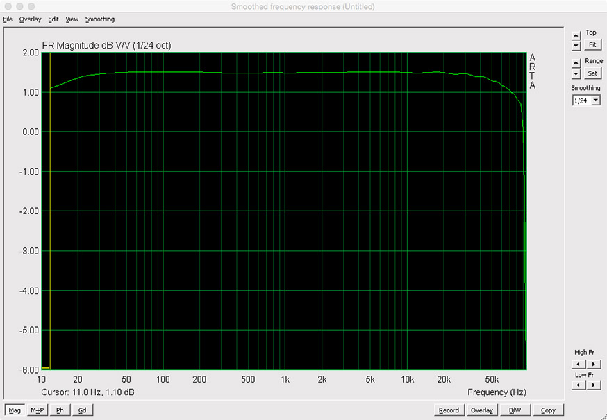
I don't think there is any way I could measure beyond about 50-60kHz as my sound card frequency response rolls off up there. See below (192kHz sample rate).
I want to make sure I am not getting confused here. I would need an FFT measurement setup with a noise floor below -120dBV at the frequency of interest - as opposed to a preamp with 120dB of gain. Right?
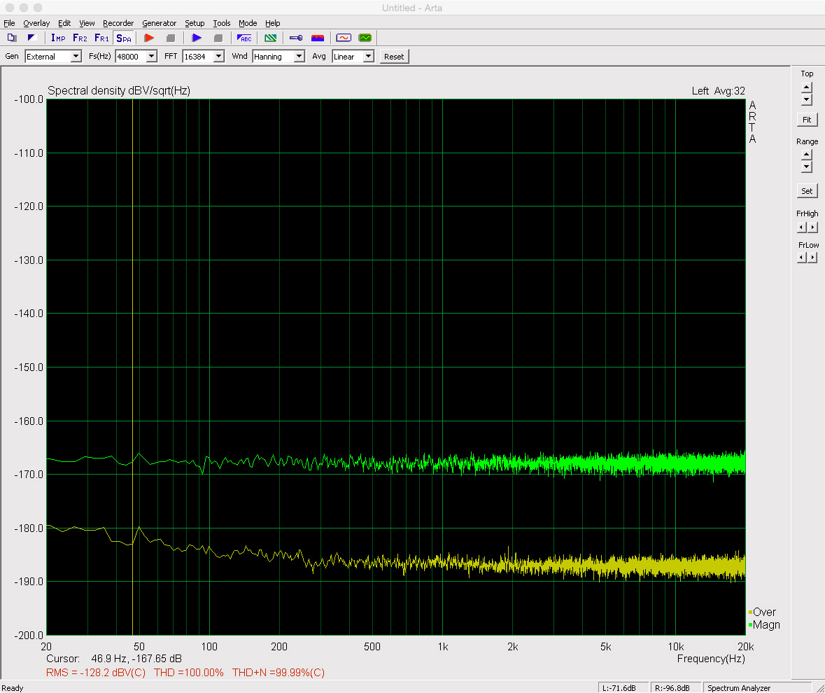
Attached is a pic of my implementation of Sam Groner's preamp with input shorted and measuring a 1k Ohm resistor.
I'll have another look at Walt's positive rail driver.
120dB preamp
I want to make sure I am not getting confused here. I would need an FFT measurement setup with a noise floor below -120dBV at the frequency of interest - as opposed to a preamp with 120dB of gain. Right?
Attached is a pic of my implementation of Sam Groner's preamp with input shorted and measuring a 1k Ohm resistor.
I'll have another look at Walt's positive rail driver.
That's a superb result.
If we assume a 1kohm has 4nV/rtHz, then that points to -167.7dBv
Near enough identical to what your plot is showing.
And your noise floor is nearly 20dB below that.
Your 50Hz interference only just shows as a tiny peak above that level. I can't pick out 3rd, nor 5th, harmonic of that mains either.
If we assume a 1kohm has 4nV/rtHz, then that points to -167.7dBv
Near enough identical to what your plot is showing.
And your noise floor is nearly 20dB below that.
Your 50Hz interference only just shows as a tiny peak above that level. I can't pick out 3rd, nor 5th, harmonic of that mains either.
Last edited:
Yes, exactly. Sorry for the sloppy and imprecise remarks above. Looking at the line regulation plots in John Walton's article, there does seem to be interesting "activity" between 20 kHz and 200 kHz that you would like your instrumentation to display. Walton and Walt Jung used a costly Audio Precision rig; maybe there simply are no practical alternatives.I would need an FFT measurement setup with a noise floor below -120dBV at the frequency of interest - as opposed to a preamp with 120dB of gain. Right?
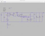
So I've been thinking about the preregulator. If we assume its function is to slice off the first 70dB of input ripple (at all frequencies), and if we don't care so much whether its output voltage is exactly 15.000 volts, as long as its line rejection is good ....
then we can tweak the output capacitor and its explicit series resistor. Instead of putting the resistor in the ground leg of the capacitor, let's put the resistor in the supply leg of the capacitor. The two topologies are equivalent: C_series_R , R_series_C {thanks to Kirchoff's Current Law} but perhaps the second one is "better" for our preregulator application.
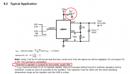
See attached figure. Now the LM2941's output sees two (capacitor series resistor) networks in parallel. The "ESR" of this network is (RsmallcapESR || Rx) and we choose component values to keep it between 0.1R and 1.0R, so the LM2941 is stable per datasheet Figure 13.
However, in this topology, the capacitors after Rx have vanishingly low ESR so they are better and better approximations of a perfect capacitor whose impedance is ~Zero. Voila, the input node of the downstream discrete regulator is a ~Zero impedance perfect voltage source. Load transients suck big impulses of current out of this ~Perfect capacitor, and the discrete regulator's input sags not at all. Not even a millivolt.
Furthermore, Rx and Cenormous provide another section of lowpass filtering, adding more line rejection.
The downsides are (i) you lose some headroom (Iload * Rx), which is probably unimportant when your input voltage is high enough to allow a preregulator; (ii) the voltage at the input of the discrete regulator is not constant, it's load-dependent: (Vlm2941 - Iload*Rx). However it moves around slowly and your downstream discrete regulator's line rejection of slow moving signals is very good.
_
then we can tweak the output capacitor and its explicit series resistor. Instead of putting the resistor in the ground leg of the capacitor, let's put the resistor in the supply leg of the capacitor. The two topologies are equivalent: C_series_R , R_series_C {thanks to Kirchoff's Current Law} but perhaps the second one is "better" for our preregulator application.
See attached figure. Now the LM2941's output sees two (capacitor series resistor) networks in parallel. The "ESR" of this network is (RsmallcapESR || Rx) and we choose component values to keep it between 0.1R and 1.0R, so the LM2941 is stable per datasheet Figure 13.
However, in this topology, the capacitors after Rx have vanishingly low ESR so they are better and better approximations of a perfect capacitor whose impedance is ~Zero. Voila, the input node of the downstream discrete regulator is a ~Zero impedance perfect voltage source. Load transients suck big impulses of current out of this ~Perfect capacitor, and the discrete regulator's input sags not at all. Not even a millivolt.
Furthermore, Rx and Cenormous provide another section of lowpass filtering, adding more line rejection.
The downsides are (i) you lose some headroom (Iload * Rx), which is probably unimportant when your input voltage is high enough to allow a preregulator; (ii) the voltage at the input of the discrete regulator is not constant, it's load-dependent: (Vlm2941 - Iload*Rx). However it moves around slowly and your downstream discrete regulator's line rejection of slow moving signals is very good.
_
Attachments
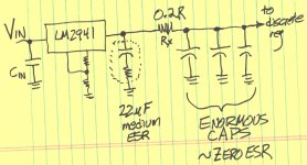
Andrew - Sam's design and board. I merely soldered it up. You will recall from the discussion in this thread that things got more complicated when it came to connecting to a DUT. I can see why the likes of John Walton, gerhard and Armand made special purpose enclosures for their tests.
Mark - ok. I was worried that I didn't understand something (as I often don't). A good sound card can do the job. It's just that I run a Mac and about the best sensibly-priced card for that is an ESI Juli@ XTe. It's max sample rate is 192kHz and as shown above its freq response suffers if one ventures too far above about 40-50kHz. For those running a Windows machine there are more options. Or, as you note, you try to borrow a costly piece of purpose-designed equipment.
Mark - ok. I was worried that I didn't understand something (as I often don't). A good sound card can do the job. It's just that I run a Mac and about the best sensibly-priced card for that is an ESI Juli@ XTe. It's max sample rate is 192kHz and as shown above its freq response suffers if one ventures too far above about 40-50kHz. For those running a Windows machine there are more options. Or, as you note, you try to borrow a costly piece of purpose-designed equipment.
So I've been thinking about the preregulator.
Interesting. (I'm glad I could understand this from the outset.) Something for a future iteration...
You could redesign Walt's ancient raildriver circuit with modern components: use an AD817 (50 MHz) and a high-fT Nchannel power MOSFET from Infineon, to give 2 amps max output current -- 1 amp for the voltage regulator under test, plus 1 amp to drive an 800nF input capacitor at 200 kHz.
Doing such a regulator to supply adequate current is straightforward - as you hinted, we've basically done this before. I've been thinking about the more challenging modification regarding where in such circuit the 1Vpp is injected. I don't really follow Walt's implementation and XLR wiring (or why his graphics seem to show 1.4Vpp input). I've been thinking about where a BNC connection from the waveform generator would be injected into the IPP037/AD817 reg circuit. Initially I was thinking it would have to be the reference part of the circuit which would have to receive the stimulus and drive change in the output, but this seemed complicated. Is it as simple as changing the reference level for the entire regulator by intercepting it and GND as depicted below? It seems to work in sim with minimal current demand placed on the injecting voltage source.
(Also, I've not worked with LTspice's FFT analysis before but it seems I can run a tran analysis and select View FFT. I guess I have to learn .MEAS statements to examine the level of distortion etc. It seems such construction has a lot of third harmonic distortion.)
Attachments
Walt installs C198 and R199 {maybe in the opposite order from my drawing?}.
Notice that R199 forms a voltage divider with the other two resistors, Rx and R1. Thus to get a 1.0V sinewave at the opamp input pin, he needs his signal generator to provide 1.4V.
Although if your sinewave generator's output impedance were really low compared to R2, you could just drive the bottom plate of C2 and be done.
_
Attachments
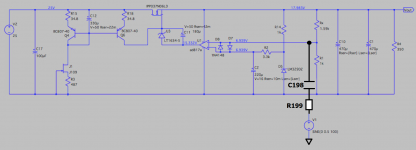
Ah. Presumably R199 is a safety current limiting resistor and C198 a DC blocking cap. And injection between inverting pin and GND. I had been looking at it like a level shift and had V1 'in series' with the op amp pin.
I wonder if I could jerry rig it onto an existing board...
I wonder if I could jerry rig it onto an existing board...
- Status
- This old topic is closed. If you want to reopen this topic, contact a moderator using the "Report Post" button.
- Home
- Amplifiers
- Power Supplies
- Thermal considerations for Fairchild SDIP bridge rectifiers