No problem ")
If anyone else is interested wiki is cached in Internet Wayback Machine.
https://web.archive.org/web/2015090...The_Wire_-_All_Boards_and_Kits_Explained_Here
If anyone else is interested wiki is cached in Internet Wayback Machine.
https://web.archive.org/web/2015090...The_Wire_-_All_Boards_and_Kits_Explained_Here
anyone ordered/paid around december?
hi DIYaudioers!
i am wondering if anybody paid for their wire pcbs around the beginning of december (30th of november in my case)? i am looking especially at orders going to europe.
my question is did you receive them yet? i know there were holidays in between, but i was just curious, since i have everything ready, all the components, just not the pcb yet
so, anybody receive theirs yet?
daniel
Hey,
Check those posts, they may clarify things a bit.
http://www.diyaudio.com/forums/head...headphone-amplifier-pcbs-246.html#post4581596
Check those posts, they may clarify things a bit.
http://www.diyaudio.com/forums/head...headphone-amplifier-pcbs-246.html#post4581596
Hello folks,
I signed up on the spreadsheet for about a month ago, but have not recieved any PM regarding the PCB's yet.
This is for a school project, I'm building a Integrated Loudspeaker and Headphone AMP and the deadline is at the end of May, therfore it is critical I get it in a reasonable time.
I signed up on the spreadsheet for about a month ago, but have not recieved any PM regarding the PCB's yet.
This is for a school project, I'm building a Integrated Loudspeaker and Headphone AMP and the deadline is at the end of May, therfore it is critical I get it in a reasonable time.
Hello folks,
I signed up on the spreadsheet for about a month ago, but have not recieved any PM regarding the PCB's yet.
This is for a school project, I'm building a Integrated Loudspeaker and Headphone AMP and the deadline is at the end of May, therfore it is critical I get it in a reasonable time.
Don't hold your breath mate...Owens gone cold...I suggest that you look elsewhere.
Hello folks,
I signed up on the spreadsheet for about a month ago, but have not recieved any PM regarding the PCB's yet.
This is for a school project, I'm building a Integrated Loudspeaker and Headphone AMP and the deadline is at the end of May, therfore it is critical I get it in a reasonable time.
I have Wire some PCBs around... tell me what you need and I will give a look tonight when I am back at home
Owen moved from Toronto, Ontario, Canada to California in the USA.
BTW, just finished up 4 LT3042 parallel regulator boards. Both halves of each worked the first time. My method for doing them without a hot-plate or oven:
1. Without a hot-plate or oven setup, you MUST use a hot-air rework station for soldering down the LT3042 to ensure the thermal pad on the bottom is soldered to the board. I use leaded thin Wonder Solder because it flows and hardens well. YMMV with other solders. Also, a good soldering iron with a very fine tip is required, temperature-controlled is best.
2. You MUST check each LT3042 for correct continuity after soldering each on before moving onto the next, NO EXCEPTIONS. Once you have more than one soldered on, finding and correcting an error (because they are in parallel) is MUCH more difficult.
3. Start by laying down a very thin layer of solder for the first LT3042 on the doubled/tripled output/input pads on the circuit board... and also on the thermal pad. The layer should show a barely perceptible bulge. Use small (.030" - .050") solder wick to remove too much solder.
4. Then tin the thermal pad on the LT3042. I hold both the solder and a small screwdriver in one hand so I can knock the chip loose if it gets attached to the iron tip. Here too you might need to use solder wick to remove excess, the pad should be tinned with no bulges or lumps.
5. Align the LT3042 on the lands. Make sure the non-paralleled leads are aligned perfectly with the individual pads. I hold down the chip with a very small screwdriver on the top and nudge it with another until perfect.
6. Spot-solder the paralleled input and output leads down to the pads. To ease this, I will touch the iron tip to the solder to get a fresh tin, then to the leads for those pads. Make sure they are attached AND all the chip leads are still perfectly aligned with the pads before continuing.
7. Using your hot-air rework gun (mine is set to 274C, yours may need to be slightly different as mine is not calibrated), heat first the backside of the board under the LT3042 for a count to 20, then the turn it over and heat the top of the chip while holding it down with that small screwdriver tip positioned to minimize blocking of the hot air, again for a count to 20. Remove the heat, wait a count of 5 for the solder to set, then put away the hot-air rework gun.
8. Inspect the LT3042 to make sure it is both now flat against the circuit board AND that the leads remained aligned on the pads. I'd try a reheat if it is not flat, I'd remove and discard if it moved (because you have to re-heat it twice, once to remove, once again to re-solder, I would not trust that chip anymore).
9. Go over the leads with the iron and the thin solder. Don't worry that it bridges, it will. Then use the solder wick LIGHTLY applied to remove the bridging.
10. Now test continuity. Pins 1-2-3-6 to the input, 4 not connected, 5-8 to ground, 7 to the set resistor pad, and 9-10 to the output resistor. Touch up if any do not connect or are shorted to their neighboring pins.
11. ONLY after you have checked out your soldering job on an LT3042 and are CERTAIN it is right, go to the next. DO NOT TOUCH UP an LT3042 you have finished after moving to the next, you might introduce shorts that are now hard to find.
12. After soldering on all the LT3042s, put on the SMD resistors, then the SMD capacitors, and finally the SMD diodes. I again do a very thin layer of solder on one pad for each, then use that small screwdriver tip to hold them down while positioning, touch the iron tip to the tip of the solder for a fresh tin, tack down the tinned side, then solder the un-tinned side and touch up the tinned side. Again, lightly use solder wick to remove too much solder build-up
13. Finally install the leaded capacitors.
And before testing it, RECHECK the LT3042's to make sure there are no shorts between pins!
I use a 9v battery with a meter set to measure current draw and another for voltage out to check each side. Current will jump to 30-40mA as the caps charge, then in a second or two drop down to about 10mA.
I hope this all helps!
Greg in Mississippi
Staus of "The Wire" project now that TE is dropping certain chips
The Texas Instruments LME49990 and LME49610 chips are at End-Of-Life.
It's difficult to obtain these chips at a reasonable DIY price. Is there a
substitute chips for each? Will they work with the present set of PCB's?
I would hate to see "The Wire" disappear from the DIY Community.
Any ideas and plans would be vital to continue the development of this great headphone amp.
I always hate when a company stops making a set of great chips.
Does Texas Instruments have drop in replacements for these two chips?
What we need is information. Take care.
Last edited:
Hi mrsavage,
I fully agree that TI EOL'ing those parts is a massive disappointment. They are phenomenal parts overall, and it's a shame that TI couldn't find a way to make them profitable even with the older fab tech.
Just the same, these are changing times, and the large volumes/profits come with highly integrated units where performance is secondary to size and power consumption.
The good news is that we have some options... The LME49600 can be replaced with the BUF634. They are pin-to-pin and mostly performance identical. I personally have never used the BUF, but many of The Wire amp builders have used them and not had any issues. Generally, it's believed that they are the same part, which I find a bit confusing.
The LME49610 does not have a replacement unfortunately. This has more of an impact on some of my other higher power amplifier projects, but not so much for the SE-SE, BAL-BAL, or LPUHP... all of which are fine with the BUF634 mentioned above. The added voltage headroom of the LME49610 allowed more power to be produced when run on parallel, and being limited to +/-18V does hurt power output on my larger amps (MPHUP and HPUHP).
As for the LME49990, that is also a pretty big loss, but there are alternatives here too. The LT1028 is a very good op-amp, and the LME49710 is also exceptional. The LME49870 is also one of the best if higher voltage output is required. I have used all three and been very happy with the results.
One proposal I would suggest is that if there is sufficient interest, I could arrange a one-time buy of a few thousand LME49610 parts and offer them along with the boards. A sufficiently large order could easily be placed with any TI distributor, and they would likely be delivered within a few weeks. My biggest issue with this is the price volatility of these parts, and the fact that if more show up on the market in the next year, the price may plummet (this happened about 2 years ago when prices for some reason dropped from about $9 per unit to about $2.30 after TI bought National. At the time I was holding a stock of a few hundred parts, and nobody wanted the kits anymore because they could get the LME parts for 1/4 of the price!
Any thoughts on the above would be welcome, and same goes for anyone who has tried any of the amps with non-standard parts. Please let the larger community know what your experience was.
Regards,
Owen
I could go for a group-buy of LME49990's, if there was interest. Digikey lists a minimum of 190 from factory stock at $2.77 USD each... I'd do 20 or so of those.
Perhaps some of the LME49870 too, even tho I haven't used them in the past.
Greg in Mississippi
P.S. Got boards today, MANY THANKS!
Perhaps some of the LME49870 too, even tho I haven't used them in the past.
Greg in Mississippi
P.S. Got boards today, MANY THANKS!
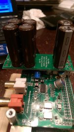
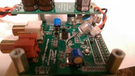
OPC's LT3042 parallel reg in the wild!
Here's a couple of pix of one of Owen's great little reg boards mounted on a HiFiBerry DAC+ Pro I abused mightily over the last couple of weeks. This nice little trick board allowed me to easily split the power feeds so that I could feed 5v to the analog side of the DAC, 3.3v to the digital side of the DAC and the two clocks (separating them from the very dirty R-Pi 3.3v), and use my base 5v to feed the R-Pi. Well worthwhile, stock it was about the same as a stock Squeezebox Touch, with the cap mods on the boards it was a bit better, but separate power feeds really lifted it a good bit.
I have now have three others built up, with one going into the DSP/Processor/Display power feed on a Sony HAP Z1-ES and the other two into modifying a pair of Soekris DAM DACs (FPGA 1.2v & 3.3v feeds).
They will take some care to build (as I outlined above), but appear to be very nice pieces of kit!!!!
Greg in Mississippi
Attachments
Hi Greg,
Awesome work with the regs and the mods!
I had originally designed them to use as bipolar supplies, but at the last minute decided to change the layout at the output to untie the two supplies and let the end user tie together for bipolar, or use separately as you have.
I'm glad I did, because I'm using more of these in applications like yours (1.2V, 3.3V) than I am in any bipolar applications where these are kinda overkill.
Anyhow, great work finding so many applications for these!
Cheers,
Owen
quote from Farnell website:
LME49610
More stock available week commencing 11/04/16 3.8GBP per IC, 3.16GBP per 10 IC
LME49990 Availability: 519 6.56GBP per IC, 4.38GBP per 10 IC
In addition to LT1028, tere is AD797 opamp, it sensetive to layout quality, but on good ruoted board, with fine bypass caps it became a performer.
My question. The decoupling capacitors suggested in BOM for WIRE PSU, those MLCC by Samsung. Is there something special about those caps ? I have a trouble to get them. Can I to replace them by X7R from Murata, Kemet or Taiyo Yuden ?
- Home
- Vendor's Bazaar
- "The Wire" Official Boards for All Projects Available Here! BAL-BAL, SE-SE, LPUHP