Hi Guys,
I reviewed the BOM and the schematic for the PSU this evening, and found that there was indeed an error in the BOM and schematic with the reference designators for the noise bypass caps, and the output bypass caps.
I have fixed both the BOM and schematic for the PSU, and reviewed it several times to make sure there were no other errors.
Jim:
My sincere apologies on this one. I usually like to reward early builders, but in this case I definitely set you back. Hopefully you can get those caps off and back where they belong on the 0805 pads.
Let me know if you have any issues, and if you need some replacement caps or a new board, I can send some your way.
Hopefully you can get it fixed.
Regards,
Owen
Last edited:
The attached photo...
You may have a solder bridge too
Attachments
Power Supply Board
Hi,
OPC: No need for a new board or caps. I am very pleased, though, that you firmly stand behind your products!
AGDR: You are correct. Funny thing is when I soldered it, I didn't catch it with my 2X magnifier. The close up macro made it stand out like a sore thumb! Thanks.
Jim
Hi,
OPC: No need for a new board or caps. I am very pleased, though, that you firmly stand behind your products!
AGDR: You are correct. Funny thing is when I soldered it, I didn't catch it with my 2X magnifier. The close up macro made it stand out like a sore thumb! Thanks.
Jim
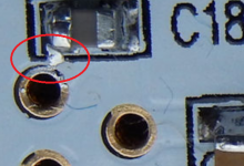
Hi Guys,
That does indeed look like a solder short, but in this case, those two pins are connected anyhow, so it should be fine.
If you look closely at the board, you can see the traces and where they connect. In the case of C87 and C18, they are both connected directly to the closest pins on the TPS reg.
This does highlight a great inspection technique that I have suggested a few times in the past. Even if you have a magnifying glass, it's a very good idea to take a few macro photos of the board from a few different angles, and inspect each one closely. I have found errors this way that I was unable to see with my naked eye.
Better yet, post the photos here and let all of us be a second set of eyes before you power up!
Another note is that the two 1210 22uF output bypass caps are in parallel and solder bridges across those adjacent terminals are also acceptable. I found these four caps to be the most difficult to solder of all the parts, but I was going for no bridges so the pictures would be pretty")
Feel free to slop these with solder as it makes no difference to performance.
Jim:
Glad to hear you can salvage the boards! Please keep us in the loop on your progress!
Cheers,
Owen
That does indeed look like a solder short, but in this case, those two pins are connected anyhow, so it should be fine.
If you look closely at the board, you can see the traces and where they connect. In the case of C87 and C18, they are both connected directly to the closest pins on the TPS reg.
This does highlight a great inspection technique that I have suggested a few times in the past. Even if you have a magnifying glass, it's a very good idea to take a few macro photos of the board from a few different angles, and inspect each one closely. I have found errors this way that I was unable to see with my naked eye.
Better yet, post the photos here and let all of us be a second set of eyes before you power up!
Another note is that the two 1210 22uF output bypass caps are in parallel and solder bridges across those adjacent terminals are also acceptable. I found these four caps to be the most difficult to solder of all the parts, but I was going for no bridges so the pictures would be pretty
Feel free to slop these with solder as it makes no difference to performance.
Jim:
Glad to hear you can salvage the boards! Please keep us in the loop on your progress!
Cheers,
Owen
Im interested in your battery pack.
Anything to share? protection? parts?
What I've made wasn't really intended for this, but just a general purpose +/-12V unregulated clean source, as most of the time stuff I do will be wanting 10-14V rails (&insensitive to exact voltage) and have on-board supplies for 5V, 3.3V etc. Also wanted USB isolation so I didn't risk destroying my laptop ports if I accidentally short something to the usb rails when probing something, so figured that can go in too.
I had a load of panny protected 18650 liions (not lipo as I said earlier) kicking around as well as a load of bistable relays so went for a setup that simply switches between charging and powering.
When charging, each cell is switched to be individually charged using its own dedicated 1 cell battery manager (MCP73831T) powered from an external supply. This completely separates the cells from each other and cuts off output 12V and downstream USB (also does not guarantee balanced charging!).
When powering, the cells are connected in series (3 positive, 3 negative) and the external supply is disconected. There is full galvanic isolation between downstream USB,12V, and upstream USB,external power.
There are buttons to flip the mode and it autoswitches to charge if USB 5V goes low.
There is no protection against over discharging cells beyond the inbuilt cut-off. This is fairly dodgy and I don't advise doing this for something that will run indefinately unattended as the limit will fail to kick in for low current draws. It's fine for my purposes as any bench testing will be short term and I'll be present. For temporary use with The Wire till I sort something better, battery life is up at about 22 hours, so not particularly an issue.
I strongly advise against doing anything with liions/lipos for something that's going to run long term unattended unless you'vve got experience of this sort of thing. It's also worth noting w/o some kind of SMPS stage after the batteries you need at least 6 cells to get the right kind of voltage which getting on too large to be portable.
Btw, strongly recommend OSHpark for prototyping PCBs. Cost me $10 a board which only marginally higher than it would've cost me to etch myself and do ENIG coating and all that jazz:
so i just finished up soldering all the smd parts for 8 lpuhp and it seems bom is wrong
r3-r5 r8-r11 is 7 not six as stated in bom is that correct for bal input 15gain ?
looked in schematic and it seems it should be r3- r5 r8-r10
I've received my boards this morning from second batch. They look superb many thanks opc
Only cons is that you can only place 16mm capacitor on the lpuhp boards and they're hard to find at mouser. I also have one board from the four with c70 cut is that normal? c6/c104 are cut on all boards.
Only cons is that you can only place 16mm capacitor on the lpuhp boards and they're hard to find at mouser. I also have one board from the four with c70 cut is that normal? c6/c104 are cut on all boards.
An externally hosted image should be here but it was not working when we last tested it.
An externally hosted image should be here but it was not working when we last tested it.
Last edited:
Hi PandazYa,
Glad they got there safely!
You happened to get the only board where I had it upside down when I started to cut what I thought was the trace on the other end of the output buffers
There is no actual copper there, so I just scratched the solder mask off. All boards have been modified in the other two locations you described.
As a note to everyone:
Please check, double check, and check again that you don't bridge those cuts when you solder those caps!
I hand tested every single board and I am 100% certain the copper was properly removed from the bottom layer, but it is still possible to re-short across the cut if you accidentally glob solder on it. I will post a specific tutorial on where to check for continuity before power up. The unwanted short basically connects the negative rail to the output, so it's important to use a multi-meter to make sure it's a high or open resistance reading from output to V-.
My board did survive for several minutes with this fault, but the output voltage on the speaker terminals was +10VDC which could easily damage a speaker. After I found the suspect traces and fixed them, the board was perfectly fine and none of the output devices or the regulators were damaged.
Nonetheless, I don't want anyone having this issue, so please be cautious soldering those caps!
Cheers,
Owen
Only cons is that you can only place 16mm capacitor on the lpuhp boards and they're hard to find at mouser.
Mouser 661-EGPA250ELL562ML4 is about the closest. See if opc would give it an OK. It is slightly different in a few parameters. Mouser shows 463 in stock.
EGPA250ELL562ML40S United Chemi-Con | Mouser
Same: 25V, 20%, 16mm diameter, 5600uF, 7.5mm lead spacing, both have 0.85 ripple de-rating at 120Hz.
Different: 40mm high vs. 37.5mm for original, 17mR vs. 10mR for original, 3.97A ripple vs. 4.2A for original, 5,000 hours at 125C vs. 10,000 hours at 105C for original.
Last edited:
Mouser 661-EGPA250ELL562ML4 is about the closest. See if opc would give it an OK. It is slightly different in a few parameters. Mouser shows 463 in stock.
EGPA250ELL562ML40S United Chemi-Con | Mouser
Same: 25V, 20%, 16mm diameter, 5600uF, 7.5mm lead spacing, both have 0.85 ripple de-rating at 120Hz.
Different: 40mm high vs. 37.5mm for original, 17mR vs. 10mR for original, 3.97A ripple vs. 4.2A for original, 5,000 hours at 125C vs. 10,000 hours at 105C for original.
I would second that! The above cap is about as close as Mouser has in stock. You won't see or measure a difference using these caps.
The only other thing I could suggest would be a GB, but those who want to get these built quickly probably don't want to wait for two months
As a side note, if anyone has a good Mouser equivalent part number list, I can add it to the spreadsheet to help others.
Cheers,
Owen
Owen,
Where have you posted the newest revisions of the BOM for the BAL and PSU? The PDF you posted a few days ago does not seem to be the most up to date.
Thanks
PSU
BOM:
https://docs.google.com/spreadsheet/ccc?key=0AnMLwB9mdXl2dDN6V05FanpQN1BFR2xRcENORVFSNXc&usp=sharing
Schematic
https://drive.google.com/file/d/0B3MLwB9mdXl2Z3N4WWh4MU93SW8/edit?usp=sharing
...
LPUHP
BOM:
https://docs.google.com/spreadsheet/...UE&usp=sharing
Schematic:
https://drive.google.com/file/d/0B3M...it?usp=sharing
Think these are what you were after, Owen updated the originals a few days ago...
Build guide for LME Power amp is in post #152. BAL-BAL headphone amp, a link to the build Wiki in post #1
Thanks agdr,
That's indeed the only one I found on mouser (in stock) that could fit the LPUHP. Now that opc has confirmed it's ok time to pull the trigger :d
Here is my mouser bom for LPUHP:
http://www.mouser.com/ProjectManager/ProjectDetail.aspx?AccessID=afa65600ba
Missing LT1185 regulators I can't find them on mouser and all resistors input gain so you can buy the one you need. Also missing from this bom is the TIM for output stage heatsink.
Edit: opc in LPUHP BOM you have count 8 diodes Schottki instead of 4.
- Home
- Vendor's Bazaar
- "The Wire" Official Boards for All Projects Available Here! BAL-BAL, SE-SE, LPUHP