flawed conclusion...............It will also be a free advert why regulated supplies are best..........
I have never seen that behaviour in any of my amplifiers. They all use conventional transformer rectifier smoothing capacitor, no regulation PSUs.
What can be done to remove, or reduce, the sticking as the amp comes out of clipping?
Andrew:
You cannot say "flawed conclusion" as a statement of fact without backing it up.
Show me. Post some close-up scope captures with a standard toroidal transformer and some caps, and show me that the rail sag doesn't influence the shape of the clipping. Remember my quotable quote from the other day?
I didn't have an unregulated linear supply handy when I took those measurements, otherwise I would have run it. I probably still will on Tuesday, but I'm hoping npdot posts his first")
Overall, I don't know how productive all this has been since we're now investigating an area of operation that nobody should be in. If you're hitting 10% THD due to clipping then you've badly underestimated your power needs and should be looking at significantly more powerful amplifiers.
Although I know some clipping is bound to happen at some point during normal use, I don't know if it's worth expending this much worry on.
As for the rail sticking at 10kHz 10%, it's just something that the LME does. I've seen it time and time again when the clipping gets severe enough. The only way I've been able to eliminate it is to use two zeners in the feedback loop to "soft clip" the output intentionally before it hits the rails.
I personally would prefer to just leave it, but the option is always there.
Cheers,
Owen
You cannot say "flawed conclusion" as a statement of fact without backing it up.
Show me. Post some close-up scope captures with a standard toroidal transformer and some caps, and show me that the rail sag doesn't influence the shape of the clipping. Remember my quotable quote from the other day?
I think that...one is all said "very well..very good" other is show real measure. without this, all are perfect..with word.
I didn't have an unregulated linear supply handy when I took those measurements, otherwise I would have run it. I probably still will on Tuesday, but I'm hoping npdot posts his first
Overall, I don't know how productive all this has been since we're now investigating an area of operation that nobody should be in. If you're hitting 10% THD due to clipping then you've badly underestimated your power needs and should be looking at significantly more powerful amplifiers.
Although I know some clipping is bound to happen at some point during normal use, I don't know if it's worth expending this much worry on.
As for the rail sticking at 10kHz 10%, it's just something that the LME does. I've seen it time and time again when the clipping gets severe enough. The only way I've been able to eliminate it is to use two zeners in the feedback loop to "soft clip" the output intentionally before it hits the rails.
I personally would prefer to just leave it, but the option is always there.
Cheers,
Owen
post1316 shows the sticking at 1kHz and all the clipping distortion from 0.1% upwards. Yes, very mild @ 0.1% and 0.5%, but it is there as far as I can see. The sticking does not only occur with 10kHz & 10% clipping distortion.
If I am reading the scope pics correctly, then running the LME at a much higher voltage than the output will help hide this sticking because the output will be clipping and hopefully the LME will not be sticking due to avoiding clipping.
Now to your flawed conclusion.
You are claiming that the sloped flat tops are an inherent behaviour of unregulated linear PSUs and that the same behaviour will not happen with an SMPS. That is the conclusion that is flawed. I have never seen those sloped clipping behaviours in any of my unregulated linear PSU powered amplifiers.
There is something odd going on that should be explained. Then you will find that SMPS is not the only way to avoid that very unusual sloping behaviour.
agree, sorry you cannot make such a statement without backup. opc did not even make a statement of fact, just a prediction and we wait for the results. until you can counter this with actual evidence, your 'conclusion' holds no meaning. i'm quite intrigued, its never likely to have any effect on my usage, but I find the explanation makes reasonable sense.
Last edited:
Like I said... show me.
If you don't have a scope capture showing the opposite then you cannot say my "conclusion" is flawed. It's also not really a conclusion, it was just a theory, or an educated guess if you prefer. I'll save the conclusions for Tuesday when I can measure the real thing. Wording is important, and I've quoted myself below with an important word bolded:
I'm willing to bet money that with the above test setup, the rail sag will cause the waveform to slope downward similar to what is seen in npdot's tests. It may not be as drastic, and I get the feeling there was a larger than normal resistance between supply and the amp which probably further exacerbated the issue, but I'm pretty sure it'll be there.
Are you sure the larger peak output to rail deltas aren't masking the issue in your other amplifiers?
Cheers,
Owen
If you don't have a scope capture showing the opposite then you cannot say my "conclusion" is flawed. It's also not really a conclusion, it was just a theory, or an educated guess if you prefer. I'll save the conclusions for Tuesday when I can measure the real thing. Wording is important, and I've quoted myself below with an important word bolded:
If it sags down and matches the shape of the clipped waveform, it will be exactly what I suspected above.
It will also be a free advert why regulated supplies are best
I'm willing to bet money that with the above test setup, the rail sag will cause the waveform to slope downward similar to what is seen in npdot's tests. It may not be as drastic, and I get the feeling there was a larger than normal resistance between supply and the amp which probably further exacerbated the issue, but I'm pretty sure it'll be there.
Are you sure the larger peak output to rail deltas aren't masking the issue in your other amplifiers?
Cheers,
Owen
I have never seen that behaviour in any of my amplifiers. They all use conventional transformer rectifier smoothing capacitor, no regulation PSUs.
Out of interest, which amplifiers?
Early results from the bench--problem resolved.
Whew! This was driving me crazy. Short explanation: my scope probe was causing the sloped clipping waveforms. I'll spare you the details but mention only that I tried and selected this one because it was the best of the bunch--but not excellent.
My apologies to all for the wild goose chase. Thanks for sticking with me.
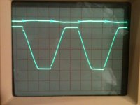
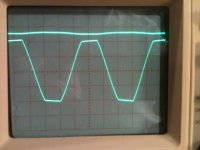
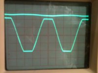
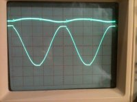
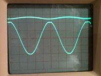
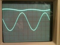
Following Owen's recommendations here are the revised results at clipping. Top trace is the positive rail at 50VDC and 2V per division. Bottom trace is the output into 8 ohms, (non inductive) at 20V per division. The PS has a 1kVA transformer (not toroidal) and 72kuF capacitance per rail.
1. 10kHz, 10% THD&N
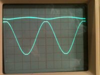
2. 1kHz, 10% THD&N
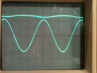
3. 100Hz, 10% THD&N
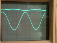
4. 10kHz, 1% THD&N
5. 1kHz, 1% THD&N
6. 100Hz, 1% THD&N
7. 10kHz, 0.1% THD&N
8. 1kHz, 0.1% THD&N
9. 100Hz, 0.1% THD&N
Although not as stiff as the DSP-600, I am satisfied with this PSU.
Regards,
Neel
Whew! This was driving me crazy. Short explanation: my scope probe was causing the sloped clipping waveforms. I'll spare you the details but mention only that I tried and selected this one because it was the best of the bunch--but not excellent.
My apologies to all for the wild goose chase. Thanks for sticking with me.
Following Owen's recommendations here are the revised results at clipping. Top trace is the positive rail at 50VDC and 2V per division. Bottom trace is the output into 8 ohms, (non inductive) at 20V per division. The PS has a 1kVA transformer (not toroidal) and 72kuF capacitance per rail.
1. 10kHz, 10% THD&N
2. 1kHz, 10% THD&N
3. 100Hz, 10% THD&N
4. 10kHz, 1% THD&N
5. 1kHz, 1% THD&N
6. 100Hz, 1% THD&N
7. 10kHz, 0.1% THD&N
8. 1kHz, 0.1% THD&N
9. 100Hz, 0.1% THD&N
Although not as stiff as the DSP-600, I am satisfied with this PSU.
Regards,
Neel
Attachments
thanks for that npdot! well done. I think this also perhaps explains both positions. your scope shots dont show the slight slanting of Owens as clearly, probably due to the measuring gear not being detailed/fast enough compared to the agilent. Possibly Andrew doesnt have access to an agilent of this quality, so may explain why he hasnt seen the behavior before. besides I dont think either is a big deal, as has been mentioned, nobody should be riding the clipping at full power.
but it does show that the dps600 more than holds its own against 1kV and 75kuF, which is a bit David and Goliath dont you think!?
but it does show that the dps600 more than holds its own against 1kV and 75kuF, which is a bit David and Goliath dont you think!?
Hi npdot,
I spot a slight rail oscillation in our 10kHz graph. It seems like a very high frequency due to the thick oscilloscope trace. Maybe some low esr capacitance in series with a L form a resonance circuit somewhere in your setup.
I good old analog scope is very useful spotting this kind of oscillations.
so it does, pic 1, 4 and 7 all show some sort of instability/resonance in the power supply rail, though the amp trace does not seem effected
yeah thats a good point, I guess a good fast analogue scope may be good, or perhaps better for spotting things that are not part of the intended measurement by being able to show very high frequency above the measurement bandwidth as a blurry trace. it does this because of its analogue nature I guess, however I would assume the agilent would pick it up also, you may need to focus in more on that higher bandwidth
yeah thats a good point, I guess a good fast analogue scope may be good, or perhaps better for spotting things that are not part of the intended measurement by being able to show very high frequency above the measurement bandwidth as a blurry trace. it does this because of its analogue nature I guess, however I would assume the agilent would pick it up also, you may need to focus in more on that higher bandwidth
Last edited:
Qusp & Opc, take note !!!!!problem resolved.
Whew! This was driving me crazy. Short explanation: my scope probe was causing the sloped clipping waveforms.
Hi,
This is not an anomaly associated with the psu. it is obvious that the DPS-600 provides a different behavior, due to the high speed of the regulator.
This ringing (also present on the measures of Owen) must be sought in the (current-limiter/ Offset sensing) of lme. ringing is a fast shutdown of the circuits of the driver, this may be due to:
a bad capacitors in the bias circuit, incorrect or need a sensing threshold for RC delay.
ringing is seen in these measures (has polarity Both neg-pos) is a "cut-off" of the stage drivers.
just to try it, you might put to gnd pin 8. This disables the output sensing sull'offest. perhaps requires a constant r-c. it's just an idea, I do not know lme.
Regards
I saw that, but it was still there very slightly and you seem to be mentioning the same pics I didQusp & Opc, take note !!!!!
opc: if this is indeed something that needs tweaking in the bias circuit, could it be your low pf thin film C79 caps for power bandwidth since we are talking about full power here? did you stay stock here with 20pf npdot?
Last edited:
Looks like my theory is debunked, although I will still run one last set of measurements with a linear PSU in my setup to confirm.
Thanks for re-measuring npdot! Much appreciated.
As for that resonance in the PSU, I would agree that it could simply be test leads that are too long between the PSU and amp board. That might cause the resonance seen in some of your scope captures. I also agree with Andrew though that this is definitely not desirable behaviour, so you might want to check your finished amp for it and make sure the problem doesn't persist.
AP2: In this case the ringing is definitely a symptom of the PSU, but the abrupt change in current demand is being caused by the amplifier's tendency to stick to the rails during clipping at high frequencies.
To this end, I have tried 4 different output stages and well over a dozen compensation schemes, and the rail sticking is always there. I'm not sure if tying osense to GND will solve the issue, but I don't see this as a viable long-term solution even if it does.
Cheers,
Owen
- Home
- Amplifiers
- Solid State
- "The Wire AMP" Class A/AB Power Amplifier based on the LME49830 with Lateral Mosfets