Andrew,
I basically agree, but at the same time I am afraid that your remarks will restart the power supply discussion, and I don't think that's a good idea....
Hi,
I really do not understand your theory. (or point of view)
Unregulated linear: you use 4.7 KuF 10KuF 100KuF or better.
apart from the reason of the ripple, you know why the sound changes? (what is the relationship with the signal going to the speaker). yes, very simple question.
Last edited:
Hi,
I really do not understand your theory. (or point of view)
Unregulated linear: you use 4.7 KUF 10KuF 100KuF or better.
apart from the reason of the ripple, you know why the sound changes? (what is the relationship with the signal going to the speaker). yes, very simple question.
You see...that's what I mean
I decided not to react anymore on power supply issues; it's pulling a dead horse, and it's not good anymore for the forum/thread.
That all of you may enjoy the Wire Amp, supplied by SMPS, linear or whatever
eheh! I knew that I would not have the answer.You see...that's what I mean
I decided not to react anymore on power supply issues; it's pulling a dead horse, and it's not good anymore for the forum/thread.
That all of you may enjoy the Wire Amp, supplied by SMPS, linear or whatever
The problem is that I encounter difficulty in explaining the reason, which is the same for all who take 100KuF. maybe it's a game convenient.
well, my game is:
use smps on amplifier if solve two points:
1) low harmonic output (at 30% of power) and low EMI / RFI.
2) capacity of the average current output, equal to 2x100KuF (minimum)
This makes sense to use a SMPS.
Last edited:

Agreed on all sides... I think it's best to drop the PSU debates as I feel like all the productive talk has already happened (and is buried amongst the less productive stuff).
I think power supplies are to audio what motor oil is to motorcycles. People have passionate and usually completely unfounded opinions about which oil is best, when the fact of the matter is that they all get the job done, and as long as you don't use something obviously wrong, you're probably going to be happy.
In the case of these supplies, use what you feel most comfortable with. Each has a series of advantages and disadvantages, and depending on your requirements, one might be an obvious choice where the other might not be a good fit. I've listened to all three, and although I have mild preferences, I can assure you that none of them sound bad.
npdot:
Thanks very much for sharing your results! I'm a little puzzled about your results between setup 1 and 2, so I'll see about re-checking them here. My initial design for this used standard IRF mosfets with a full thermal compensation circuit, and that amplifier showed obvious deltas with higher LME voltage, but it looks like the laterals don't show quite as pronounced a difference.
I have noticed that with the non-lateral fets you could literally bang the output right into the rails given a high enough delta between the LME rails and the output (usually between 8V and 15V higher depending on the FET). With the lateral fets, you don't get the same behaviour presumably due to the higher ON resistance.
Still, from what I remember I was getting closer to the rails than that... Usually within 4-5V without any clipping, and often less than 4V if you use 1% THD+N as the "clipping" level.
See the attached scope screenshot for reference.
Cheers,
Owen
Attachments
npdot:
Out of curiosity, how do you define "1VRMS below clipping"?
Is clipping:
- The first visual sign of a distorted waveform on a scope?
- The point where THD climbs above 0.1%?
- The point where THD climbs above 1.0%?
- The point where THD climbs above 10%?
- The moment distortion climbs above 0.003%?
I'm just curious because all are technically acceptable but there is obviously a lot of variance in output levels.
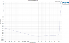
If you look at the attached image for the amp with the DPS-400 power supply, you could say the "clipping" level is anywhere between 100W and 175W depending on how you define it.
Cheers,
Owen
Out of curiosity, how do you define "1VRMS below clipping"?
Is clipping:
- The first visual sign of a distorted waveform on a scope?
- The point where THD climbs above 0.1%?
- The point where THD climbs above 1.0%?
- The point where THD climbs above 10%?
- The moment distortion climbs above 0.003%?
I'm just curious because all are technically acceptable but there is obviously a lot of variance in output levels.
If you look at the attached image for the amp with the DPS-400 power supply, you could say the "clipping" level is anywhere between 100W and 175W depending on how you define it.
Cheers,
Owen
Attachments
Owen,
Good questions. At the first the visual signs on the scope, the residual from the analyzer is excessive. By backing off of the amplitude until the residual is reduced to a minimum was approximately 1Vrms. Since 1Vrms is fairly small I didn't feel that finding the 1.0% point was that interesting. I can repeat the tests easily. What threshold would you like me to use?
Neel
Ndot,
how visible are the clipping of those waveforms?
I back off until the visible flattening is "just" not visible. I don't know what that distortion level is, but that becomes my version of the output voltage for maximum power and maximum Vpk into the specified load.
I do know that I am not in the 10% region of clipping distortion. I suspect I am below 1% of clipping distortion, but that is a guess.
It would be nice to see pics of what 0.1%, 0.2%, 0.5%, 1% and 2% of clipping distortion looked like. and the relative Vpk is for each.
Hi Anders,
I have done some preliminary tests at 10K and 20K with 80K BW. As with almost all amps this one has higher THDN at higher frequencies due to the reduced level of global feed back at higher frequencies, necessitated by phase shift related stability requirements. So, I prefer to hear from the guys with access to the state-of-the-art A-P gear to really understand what's happening "up there". As for IM, my bench IM measurement capabilities are inadequate. The HP 339A is strictly for HD.
The reason for my post #1279 was to focus on the "On" resistance issue and the benefits of a separate LME supply from one for the OPS.
However, let me go on record as saying that distortion at 10K and 20K is not as important as at lower frequencies. For example the second harmonic of a 10K Hz signal is 20K Hz, well beyond my hearing, probably well beyond the hearing of most people. The second harmonic of 20K Hz is 40K Hz, etc.
I really am enjoying this thread and the great folks participating. Thanks for your contributions.
Neel

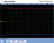
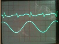
AndrewT,
Here are the scope traces for my test #1 scenario. The bottom trace is the amp output; top is the residual from the analyzer. You will notice that in the 1% case, the residual and the notches in the output waveform correspond. For the 0.1% case only one of the notches is still visible. For 0.01% the notches are completely invisible in the trace. The distortion residual, however, shows where the clipping notches would be seen if the scope could resolve them. The scope settings are the same in all three pictures.
Neel
Attachments
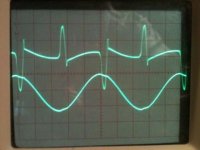
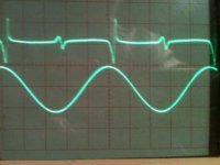
I cannot see the flat tops on either the 0.1%, nor the 0.01% distortion waveforms.
I can see flat sections near the top of the 1% waveform. But I would not call them flat topped. The straight bits are sloped and seem to start after the top and then carry on down the slope.
Why are the flat bits not at the top?
When I look at clipped waveforms on any of my amps I see the flat tops at the top.
- Home
- Amplifiers
- Solid State
- "The Wire AMP" Class A/AB Power Amplifier based on the LME49830 with Lateral Mosfets