Just one question as I didn't follow complete thread... DPS600 is suitable for both LME and mosfet voltage rails? I mean I can use one DPS600 for one channel? I can set...for example 65/55V on DPS600?
One dps-600 supplies both voltage eg. +/-68V and 85V for lme (or other difference,that Owen advice)
yes, one dps-600 for one amp (independant of power)
Is possible VADJ (trim on board) +/-5% Vout (lme follow in proportion)
thanks Igor I am getting lost now the it's such a long thread!
but.. thas this means the LME would be fed by a regulated segment on the supply?
cheers.
with DPS600, both the high current and higher voltage driver stages are regulated, you dont get step response like that with unregulated normally, even with the whole case full of caps
Hi Guys,
Just for clarity, the main power rails for the mosfets are going to be directly regulated (the feedback point is almost always taken from the highest power rails) and the higher voltage rails will technically be regulated, but only by virtue of the higher power (LV) rails being regulated. The HV windings, depending on how they are done, will either be entirely separate, or additional windings added to the LV winding.
For this reason, I'd suggest adding in the optional linear regulators that already have place holders on the DPS-600 PCB. Adding these will basically add a second regulation to the HV rails, and prevent things like climbing voltage on these rails when the LV rails are heavily loaded. IMO, this would be the most ideal setup, as it provides two fully and directly regulated rails, one for the LME exclusively, and another for the mosfets.
Roberto can probably shed more light on the feedback and regulation scheme, as the above is just a guess from experience. You only run into problems with the following two scenarios:
1. Having a heavy load on the LV rails with a light load on the HV rails will cause the HV rails to increase in voltage. (This will be a common scenario for this amp, as the LME always draws the same low current)
2. Having a heavy load on the HV rails while the LV rails are lightly loaded. In this case, the HV rails will droop. (This should never happen with this amp)
Adding post regulation on the HV supply eliminates #1 as a problem.
These rails should be 10-12V apart, and it's a good idea not to exceed 85V on the LME as the little heatsink it's on will get pretty toasty
Regards,
Owen
Last edited:
Hi all,Hi Guys,
Just for clarity, the main power rails for the mosfets are going to be directly regulated (the feedback point is almost always taken from the highest power rails) and the higher voltage rails will technically be regulated, but only by virtue of the higher power (LV) rails being regulated. The HV windings, depending on how they are done, will either be entirely separate, or additional windings added to the LV winding.
For this reason, I'd suggest adding in the optional linear regulators that already have place holders on the DPS-600 PCB. Adding these will basically add a second regulation to the HV rails, and prevent things like climbing voltage on these rails when the LV rails are heavily loaded. IMO, this would be the most ideal setup, as it provides two fully and directly regulated rails, one for the LME exclusively, and another for the mosfets.
Roberto can probably shed more light on the feedback and regulation scheme, as the above is just a guess from experience. You only run into problems with the following two scenarios:
1. Having a heavy load on the LV rails with a light load on the HV rails will cause the HV rails to increase in voltage. (This will be a common scenario for this amp, as the LME always draws the same low current)
2. Having a heavy load on the HV rails while the LV rails are lightly loaded. In this case, the HV rails will droop. (This should never happen with this amp)
Adding post regulation on the HV supply eliminates #1 as a problem.
These rails should be 10-12V apart, and it's a good idea not to exceed 85V on the LME as the little heatsink it's on will get pretty toasty
Regards,
Owen
Explanation flawless, then proceeds to +12 V LME.
Also, it is more practical to have no other board in connection.
Today later , as promised i show some photos and all features of this smps.
regards
Consider that, hv (lme) is the output of this Aux SMPS, this output is in any case under controllers (onboard or external) and works only with constant loads.
sorry, I was busy, I did not read well the point (2).
in this case, there is no variation. (variable load on aux,not produce variation on power DC).
sorry, I was busy, I did not read well the point (2).
in this case, there is no variation. (variable load on aux,not produce variation on power DC).
qusp, did you sent PM to AP2? Did you manage to get any information about sending PS from manufacturer?
this is the only way its going to work. actually no i've had my hands/head a bit full, but anything else would be a big waste of money, particularly for us outside EU. i'll drop him a note now, though hes watching the thread its probably best by PM.
Hi Guys,
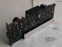
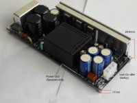
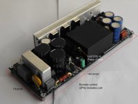
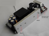
Think all know, just put on thread a standard version of DPS-600 suitable for this good Wire Amp.
Is better I finish datasheet instead put some features.
Just Important ..this model not work at 110Vac.
Some note on pic, as dimension, screw etc.
regards
Think all know, just put on thread a standard version of DPS-600 suitable for this good Wire Amp.
Is better I finish datasheet instead put some features.
Just Important ..this model not work at 110Vac.
Some note on pic, as dimension, screw etc.
regards
Attachments
How many DPS-600 and what voltage do I need?
-joe
Depeand what is your target
Audio Power SMPS GB
Emphrygian x 2- DPS600 - around +/-60V
igor0203 x 2 - DPS600 - +/-65/55V
qusp x 2 - DPS600 - +/-55V +/-5%
lolo x 10 DPS600 - +/- 50/60
QRikard x 2 DPS600 - +/-45V (55V works as well)
Wirewiggler x 2 DSP600 +/- 55V
BuildMeSomething x 2 DSP600 - +/- 55V
johnwallis x 2 DSP600 - +/- 55V
neb001 x2 DSP600 - +/- 55V
26 DPS600 so far")
well that depends, since AP2 has said there will not be a 110v version, so if you dont have access to 220-240v mains or a stepdown transformer, it seems these people are out of luck in this case.
How many DPS-600 and what voltage do I need?
-joe
see above, this is the more pressing question, do you have 220-240v available?
Hi Guys,
Think all know, just put on thread a standard version of DPS-600 suitable for this good Wire Amp.
Is better I finish datasheet instead put some features.
Just Important ..this model not work at 110Vac.
Some note on pic, as dimension, screw etc.
regards
I think initially this might be a good idea mate, just get these ones that are already suitable for 220-240v out there instead of getting bogged down in changes since we can manage the dps600 as is with some simple additional circuit to raise bias after initial lower setting. so do I remember correctly that you have enough in stock to cover the order as it stands (there will probably be a few less than 26 given the 110v only.
it would seem so i'm afraid. if there is enough demand they will probably make a 110v, but available stock does not. to be fair that was stated from the start and part of the reason opc took some time getting the testing done as he could only do it at work. but probably there will be increased demand after more get out there and you may even get a better supply with updates. so maybe just go with a linear supply using parts you may have on hand (I can probably even send you some caps mate) and watch this space I guess.
to do the 110v version there will be a whole new set of EMC testing that is needed, part of the reason Owen backed out of supplying them I presume. the dps500 on the other hand may be available in 110v, but dont quote me on that
to do the 110v version there will be a whole new set of EMC testing that is needed, part of the reason Owen backed out of supplying them I presume. the dps500 on the other hand may be available in 110v, but dont quote me on that
Hi,
The standard version is in stock. For this model, the GB can help you get a small discount to the already low price (see dps-600/DA).
One note is that this version (will update and present only on site but not online shop), the reason is that this model is used in other areas (no audio), due to the weight and size, and the very low EMI emission / RFI.
This ensures a continuous production of the standard version.
As discussed earlier with Owen, it would be possible to 110V model.
This, however, has two limitations. only 105-125Vac or 230Vac and output voltage up to 50V (+65 lme). other than that, must be rebuilt compatibility (EMC) (SMPS have this certification), I do not think it can be addressed at this time, but if some company is interested, I think you can change everything.
I think the standard version allows to create a monoblock with new design, very compact for powers up to 400Wrms (4R) in class AB with new performances on audio, this is not little.
Regards
- Home
- Amplifiers
- Solid State
- "The Wire AMP" Class A/AB Power Amplifier based on the LME49830 with Lateral Mosfets