I have taken on board the health and audio warnings of the effects of radio waves........ not using wifi in the house means theres no wifi in the house?
............
I have deliberately avoided having any radio transmitters in my house.
The one exception is my phone.
unregulated: dimension 100x100mmx36 (include active ripple power filter).
this last smps, support up to 2x10.000uF/63V at output.
Regards
Roberto:
Does the smaller PS have the option for remote on/off?
Even though it's unregulated, it's certainly a nice little unit

http://www.audiopower.it/datasheet/DPS400-52_EN1-3.pdf
Mark, i wouldnt worry too much, it would be nice for sure, but we are working on all that stuff for the lpuhp and i plan to extend it to these with the addition of more Xbee's so the whole unit would be switched off along with the other (in my case) 4 channels simultaneously. i'm liking the look of the DPS500S-D i do love german engineering, but damn 750EU for 4 channels, u wonder if we will be able to organize a special buy page for the GB? =P i could perhaps buy just 2 channels to try out and go linear on the other 2.
i'm still considering lashing up a fully regulated linear supply and will be doing some experiments to that effect.
i'm still considering lashing up a fully regulated linear supply and will be doing some experiments to that effect.
Found that SMPS on the Audiopower web site and it is less than $100 AUD....
DPS-400
I really hope it tests as well as Roberto is suggesting as it seems almost perfect for these amps. At about 4"x4"x1.5" it compliments the compact size of the amp modules too.
Edit:
Yeah, it's not an issue at all I'm just curious as it eliminates an extra relay and keeps wiring clean and simple. (The bigger Audiopower supplies definitely have the option of remote on/off) Oh, and they're Italian by the way.
Last edited:
Roberto:
Does the smaller PS have the option for remote on/off?
Even though it's unregulated, it's certainly a nice little unit
http://www.audiopower.it/datasheet/DPS400-52_EN1-3.pdf
Hi,
Yes, can be as DPS-500/S same scheme remote control. 4pins connector.
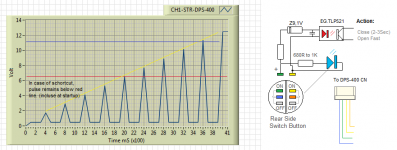
Ideal for E-Switch,circular button with led. "Led have active functions"
pulse at start for 1-3Sec. or pulse for protection. off immediately.
I'm waiting for the test Opc (not knowing if.. it's a good SMPS)
but for any adjustment considering the type of amplifier. particularly in the startup sequence.
After test, i explain why this smps not use chip pwm.
Regards
Well, colour me interested!
So Roberto it latches on after 2-3sec pulse on control wire? What is the voltage required on control circuit?
Hi,
after 1-3 sec, permanently illuminated. if you mean voltage of led,it drive up to blue led. (3-4V via resistor) on this pins. but, after startup sequence, in this pins, are present 12-14V. it is possible use also for driving mini-relay for protection on amplifier. some use this with photodiode eg. tlp521, then obtain..delay on start and fast switch-off of relay.
Ah sorry. Was a misunderstanding, I hadn't read the DPS-500/S datasheet when I posted. I made a poor assumption, that remote control was by an onboard relay that would need an active input to set the on/off state of the PSU.
Thanks for the info!
Oh, and they're Italian by the way.
haha Freudian slip i guess, must have been the $$$
regardless i'm starting to get more interested, need tests to assure my fragile sensibilities though. the design is quite intriguing and the board is sexy as hell. decent chunk of change but you can at least see where the money went
Last edited:
Hi,
after 1-3 sec, permanently illuminated. if you mean voltage of led,it drive up to blue led. (3-4V via resistor) on this pins. but, after startup sequence, in this pins, are present 12-14V. it is possible use also for driving mini-relay for protection on amplifier. some use this with photodiode eg. tlp521, then obtain..delay on start and fast switch-off of relay.
What he wrote there is a big deal for anyone looking for a very clean and simple solution to overall startup, shutdown and speaker protection.
All you would need is a single relay on the loudspeaker output, with the coil wired up to this supply. If I'm understanding AP2 correctly, then this would delay the turn on of the relay by 3 seconds which would eliminate any chance of turn on transients, it would open the relay in the event of a supply failure (short on output etc...) and protect the loudspeaker in the event of supply problems, and it should presumably open the realy on shutdown.
Now that's built in convenience!
AP2: Can you better explain exactly how this scheme works? Is there a datasheet that explains the ins and outs in detail?
Regards,
Owen
opc: in this scenario you have a relay actually IN the speaker output lines? or do you just mean in the main high current PSU output which only connects to the output stage? without a lot of capacitance it would seem ok to just switch off the power.
I dont like the idea of a relay in the speaker output directly at all and not sure that represents a clean solution if thats what you mean, everything else sounds great and exactly the sort of thing we want, perhaps we could make our own mosfet based switch in place of the relays.
some are made better than others and a knife switch or perhaps amplimo might be ok, but hmmmm i think i would rather skip that
ap2, is there i2c comms as well? yes if there is some sort of technical document that covers this that would be great
What he wrote there is a big deal for anyone looking for a very clean and simple solution to overall startup, shutdown and speaker protection.
All you would need is a single relay on the loudspeaker output, with the coil wired up to this supply. If I'm understanding AP2 correctly, then this would delay the turn on of the relay by 3 seconds which would eliminate any chance of turn on transients, it would open the relay in the event of a supply failure (short on output etc...) and protect the loudspeaker in the event of supply problems, and it should presumably open the realy on shutdown.
Now that's built in convenience!
AP2: Can you better explain exactly how this scheme works? Is there a datasheet that explains the ins and outs in detail?
Regards,
Owen
Hi,
I think the ability to connect a switch with light (remote control) directly on the SMPS can simplify installation and make it clean, no other pcb to add.
but if someone wants to use this function, then it is simple.
Notes: The main reason for this circuit , similar to a ramp generator, the SMPS to provide an effective protection, especially during startup. Indeed, one problem is just when the short circuit is already there When switch-on.
Regards
Attachments
And if you do, will you need to change the compensation capacitor or resistor values a bit?
And posts 636 643
The multi device amps I've seen and used over the years did not use a source resistor in each MOSFET. Just paralleled them. The internal Ron is about 12 Ohms isn't it, I've forgotten just now? You could add a 22pf across G and D to deal with high frequency oscillating; an effect the Semelab Alfets don't have. I like the idea of using single die MOSFETs as it get the heat out better, and as the internal resistance goes up with heat, which you don't to happen. It costs more though and I don't know how significant the effect might be.
The 2SK1058/2SJ162 certainly would work, but you'd need at least 2 of each of them to get equivalent power dissipation and current. DK has them listed at $10 each so with three of them it would effectively triple the cost for only a slight increase is dissipation and current capability.
Just the same, if someone wants to drop the mosfets from their order and try these, they would most likely work just fine.
Cheers,
Owen
And posts 636 643
The multi device amps I've seen and used over the years did not use a source resistor in each MOSFET. Just paralleled them. The internal Ron is about 12 Ohms isn't it, I've forgotten just now? You could add a 22pf across G and D to deal with high frequency oscillating; an effect the Semelab Alfets don't have. I like the idea of using single die MOSFETs as it get the heat out better, and as the internal resistance goes up with heat, which you don't to happen. It costs more though and I don't know how significant the effect might be.
Last edited:
Regarding what I said pages ago about my effective use of a simple series pre-regulator to cut high frequency noise from a SMPS, or in my case it was a clock module, I just stumbled upon these pages where some kindly person has scoped and posted with some explanations:
Using 3-pin regulators off-piste: part 2
Hear it in the one drop
Using 3-pin regulators off-piste: part 2
Hear it in the one drop
yep, keen to hear about that, i have some DPS-500/S loaded in the cart at Audiopower, maybe even just one will do for now for 2 channels and EX tax the price is not too bad. since the tweeters will now likely be powered with the LPUHP and the other 2 wire power amps probably destined for some subs not yet built the expense is not so huge.
- Home
- Amplifiers
- Solid State
- "The Wire AMP" Class A/AB Power Amplifier based on the LME49830 with Lateral Mosfets