Alex
Thank you for your efforts in laying out these PCB's.
If I have any criticisims hopefully they will be taken constructively.
The Gate resistors (100R) should be positioned as closely to the output mosfet gate connection as possible.
I am interested in why you have added the current sharing resistors to the mosfet source output connection? These resistors are used on vertical mosfets, but are not necessary for lateral mosfets due to the negative temperature coefficient. The resistors are not on the original schematic. There are none of these resistors on any of the 9 lateral mosfet power amplifiers I own!
Thank you for your efforts in laying out these PCB's.
If I have any criticisims hopefully they will be taken constructively.
The Gate resistors (100R) should be positioned as closely to the output mosfet gate connection as possible.
I am interested in why you have added the current sharing resistors to the mosfet source output connection? These resistors are used on vertical mosfets, but are not necessary for lateral mosfets due to the negative temperature coefficient. The resistors are not on the original schematic.
There are none of these resistors on any of the 9 lateral mosfet power amplifiers I own!Alex,
A beautiful board, very elegantly laid out. Not easy, takes a lot of time and effort.
I'm not sure how you'd get around this, but yes, I agree with Xoc1 who suggested putting the gate stoppers near the device gate. It would require a lot of difficult rearrangement, but I do feel it's necessary. This is my only issue with your otherwise magnificent board design.
Hugh
Anybody know why MPSA73/43 is used instead of the more common MPSA72/42? MPSA72/42 has higher breakdown voltage and lower collector input capacitance (hence a preferred device).
Logically, higher breakdown will have compensation somewhere else like noise figure, but it isn't shown in the PDF. Anybody know that the MPSA73 is really better? It seems to me that the component choice is well thought of in this circuit. I'm sure many will be happy with the result of this amplifier, tho some few other builders may have gone a few step further.
Logically, higher breakdown will have compensation somewhere else like noise figure, but it isn't shown in the PDF. Anybody know that the MPSA73 is really better? It seems to me that the component choice is well thought of in this circuit. I'm sure many will be happy with the result of this amplifier, tho some few other builders may have gone a few step further.
Jay - The transistor pair is Motorola MPSA93 and MPSA43, not MPSA73.
A lot of the particular parts have been picked for a reason for this amp. Changing parts might make it unstable.
I love that in this new board the MOSFETS are all on one side. Makes it easier to construct heatsinks. I also like that they are mounted closer to the edge.
The 100R resistors and 10nF capacitors should be as close to the MOSFETS as possible.
The BSS71/BSS74 transistors do not need a heatsink.
The BD249C and BD250C should really be mounted on the main heatsink with the MOSFETS.
Can you please add the 100uF/100V capacitors from the main power supply back on the board? It's the ones that would come right after and in parallel to the 10,000uF/100V capacitors.
I can live with the 10,000uF capacitors being off the board. Although it would be nice if they were on it.
The 0.22R/4W resistors are not needed.
The 0.1uF/160V and 100nF/250V capacitors are not needed.
The rest of the schematic and layout looks terrific. With these few changes, the amp should work great.
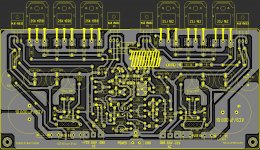
PCB rev 2.2 ......final one
Thanks guys , this time after many hours playng with my mouse , the job have done .I thing now it's quite good , if not I'm open to take critics from you .
Regards Alex .L.E. Error caps are 10.000 uF /100 vV not 63V like in the picture !
Thanks guys , this time after many hours playng with my mouse , the job have done .I thing now it's quite good , if not I'm open to take critics from you .
Regards Alex .L.E. Error caps are 10.000 uF /100 vV not 63V like in the picture !
Attachments
Last edited:
Alex,
you are quite gifted in this pcb thing. What are the finished dimensions of this final all on one side layout?
I think this will make a very nice amplifier. I like the two big onboard caps.
Does anyone want to make some boards for a group buy. There is already significant interest.
Tad
you are quite gifted in this pcb thing. What are the finished dimensions of this final all on one side layout?
I think this will make a very nice amplifier. I like the two big onboard caps.
Does anyone want to make some boards for a group buy. There is already significant interest.
Tad
Alex,
you are quite gifted in this pcb thing. What are the finished dimensions of this final all on one side layout?
I think this will make a very nice amplifier. I like the two big onboard caps.
Does anyone want to make some boards for a group buy. There is already significant interest.
Tad
Hi
I second that... I would be interested too. Can this run in balanced mode using two boards?
Thanks.
TC
Alex - This final board is an absolute perfection!!!!!!!!!!!!!!!!!!!!!!!!!!!!!!!!!!! This is the one I want! No need to tinker with anything else Who can organize the group buy? I'm 100% in.
janpo - This amplifier will not work properly with 35V. Take a look at some Hammond transformers. 100-200VA/60V are not expensive at all and work perfect for this amp.
TC Goh - This amp is not a true balanced amp, most good amps aren't. You can still install XLR connectors if you'd like to.
Who can organize the group buy? I'm 100% in.janpo - This amplifier will not work properly with 35V. Take a look at some Hammond transformers. 100-200VA/60V are not expensive at all and work perfect for this amp.
TC Goh - This amp is not a true balanced amp, most good amps aren't. You can still install XLR connectors if you'd like to.
A few transistors have been mislabled: BC546B and BC182B.
I would also recommend sticking with MPSA93/MPSA43 pair instead of MPSA92/MPSA42.
The main power supply voltage should be +/- 80V and not 70V.
And as was already indicated, the main power caps should be 100V and not 63V.
Also, is MJE15032/MJE15033 really equivalent to both BD249c/BD250C and BSS71/BSS74? They might work fine, but the specs are definitely not the same, so the amp might not perform 100% as it should. Is there any way to slightly modify the board (to make more room so that BD249C/BD250C will fit and also that the metal can tripod BSS71/BSS74 will mount right) that for those who want to buy these original schematic NOS parts would be able to do so? That would be great!
Last edited:
Hi Alex,
Do you think it will be better if there is mechanical support at the top of the board too?
FR-4 1.6mm
Dimension : 162 x 87mm
Copper tk : 2 oz, tinned, single side with soldering mask
white silkscreen printing on component side
if that is the spec. for it, I will try to get a quote from my pcb fab house tomorrow.
The main power supply voltage should be +/- 80V and not 70V.
QUOTE]
160V total PS while the 2SJ49/2SK133 are rated at 140V max...
Before giving such advices that can turn costly to eventual builders,
i can only advice you to make some more serious research about the
used components...
wahab - I'm not sure I understand what you're talking about. The MOSFETS are rated for 140V, they are being fed 80V. What exactly is the problem? The voltage should be +/- 80V. You can certainly use 70V, but then you're deviating from the schematic and I cannot guarantee that the amp will function 100% like it's suppose to.
It will work in a wide supply range...
At full power, the devices will withstand the full rails
voltage, that is 160V...
2SJ49/2SK134 are rated 140V
2SJ50/2SK135 are 160V...
You should use these latters if you want to squeeze out
the last drop from this design, but for safety reasons, even
using the higher voltage grade , it s better to have about +-70V
at most..
These Hitachi devices are rugged and can easily take a little more
voltage than their rating, but it s better not to dare the devil...
Last edited:
- Home
- Amplifiers
- Solid State
- The Very Best Amplifier I Have Ever Heard!!!!