This amp can drive just about anything. It's an unbelievably fast sounding amplifier. Very dynamic, clear, yet not harsh, or shrill sounding. I've used it with the following speakers: Goldmund Dialogue, Goldmund Prologue, Goldmund Logos Mini, Goldmund Super Dialogue, Goldmund Logos1, Ensemble PA-1, Ensemle Reference, Ensemble Animata, etc.
One of the most popular speakers I used to deal with were the B&W line. I personally strongly disliked these speakers. I once used this amp to run a pair of B&W N802s and they actually sounded terrific!
One of the most popular speakers I used to deal with were the B&W line. I personally strongly disliked these speakers. I once used this amp to run a pair of B&W N802s and they actually sounded terrific!
What is wrong with the extra pair of outputs on the pcb. You do not have to use them. If their are four then it appeals to a larger group.
With 160V from rail to rail a lateral mosfet amplifier might be expected to produce 450W into 4 ohms, maybe a little more with a massive power supply. So 3 pairs of 150W mosfets are probably OK to drive one pair of speakers. This amplifier is not a PA amp, It has wide bandwidth and will need to be driven with a signal with neglible DC offset, and impecable RF behaviour. If you look at the schematic you may notice the complete lack of any capacitors in the signal path. After all the best sounding capacitor is no capacitor!Frequency bandwidth is +/- 3dB from 0Hz-1MHz.
This is a wide bandwidth amplifier
It takes more than this basic schematic to extract the good
juice of lateral mosfets...
Large bandwith is not all.
Expect high levels of THD since the sim is made
at a modest 64W RMS, way under the claimed 200W+...
juice of lateral mosfets...
Large bandwith is not all.
Expect high levels of THD since the sim is made
at a modest 64W RMS, way under the claimed 200W+...
Attachments
Last edited:
I've worked in the audio industry for more than 10 years, this is by far the very best amplifier I have ever heard and I've heard them all.
An externally hosted image should be here but it was not working when we last tested it.
An externally hosted image should be here but it was not working when we last tested it.
An externally hosted image should be here but it was not working when we last tested it.
Let's see , pix 1 is just about the most common cascoded JFET input stage of the 80's (pioneer , luxman , sansui , many others). A very good setup for a differential ... reliable. Pix 1 has a overly crude CCS
 . I use a slightly more advanced version of it in 2 of my amps,(attachment 1) the CX and GX.
 PIX 2 is a VERY crude symasym type balanced VAS , infact ... trying EVERY variant of this particular circuit , I know why Wahib's simulation shows lousy performance. The symasym's VAS or my CX (attachment 2) would be many times more linear in the worst case.
Pix 3 ...I really cannot understand WHY... if they went to the trouble of running a totally separate supply for the input/VAS , did they not design a truely regulated one instead of that "cheesy" half wave rectifier/capacitance multiplier "trainwreck". It would work , but I have the taps on my rig to feed my better capacitance multiplier with a REAL regulated supply if I wanted to. I bet the 60V AC came off the same trafo as the main rails.
And last , why would one design a board or even consider a group buy without simulating and/or prototyping the circuit first. I would , but am too poor to afford the laterals. I am almost "over-familiar"
 with the input stage , voltage stage and the use of a split PS.
OS
Attachments
I aggree with ostripper.
Nobody has done a simualtion.
I think there would be some diy'er, who are willing to buy the pcb, but have no scope at home.
The design and the board have to be check first.
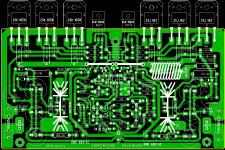
We have done the pcb for this lineamp
http://www.diyaudio.com/forums/analogue-source/154210-mpp-143.html
Post 1430
Here is the pcb
http://www.diyaudio.com/forums/analogue-source/154210-mpp-148.html
Post 1479
Although ther was no osscialtion problem with the p2p, there was a little one
with the pcb setup. We have to compensate the design on pcb.
And then, there is superb sound that can be rebuild by any diy'er
With kind regards
SAm
Nobody has done a simualtion.
I think there would be some diy'er, who are willing to buy the pcb, but have no scope at home.
The design and the board have to be check first.
We have done the pcb for this lineamp
http://www.diyaudio.com/forums/analogue-source/154210-mpp-143.html
Post 1430
Here is the pcb
http://www.diyaudio.com/forums/analogue-source/154210-mpp-148.html
Post 1479
Although ther was no osscialtion problem with the p2p, there was a little one
with the pcb setup. We have to compensate the design on pcb.
And then, there is superb sound that can be rebuild by any diy'er
With kind regards
SAm
Nowadays, i can only warmly recommend Hitachi s laterals..
It happen that my everyday 24/7 amp make also use of three
pairs of 2SJ48/2SK133 , which are the 120V versions of these
devices, and it seems that THD is not a concern audibly speaking.
The TOP3 versions are 2SJ162/2SK1058 for the most voltage rugged
versions, although they have a slightly lower voltage threshold that
their old brothers, but set apart this parameter, they are exactly the
same devices..
No DC in output
It is common knowledge that the best amps have little if no DC in the output signal and that very low if no DC in the input signal. If we conclude that capacitors are considered taboo in the signal path, either the output of the preamp or the input of the power amp, then aside from a transformer how do we completely eliminate the DC component?
Would a small transfer at the inputs or large ones at the output be the best way to approach this problem?
I thought this amplifier was a tried and true design. Is a beta test of a built amp necessary before several a distributed. If and when.
Tad
- Home
- Amplifiers
- Solid State
- The Very Best Amplifier I Have Ever Heard!!!!