Hi Alex,
Can you send me the 6 files (Top silkscreen, Top resis, Top, Bott, Bott resis, Drill). Just want to see if I can read then (or should i say, the fab house). It would be aweful if I get all the orders and find that I cannot take you files to fab. Like I said, a previous sample will be good enough. Just want to see if I can recognize files generate by your pcb software, just in case.
Can you send me the 6 files (Top silkscreen, Top resis, Top, Bott, Bott resis, Drill). Just want to see if I can read then (or should i say, the fab house). It would be aweful if I get all the orders and find that I cannot take you files to fab. Like I said, a previous sample will be good enough. Just want to see if I can recognize files generate by your pcb software, just in case.
perhaps a single board should be done first and verified to ensure it actually works as designed?
I second that. I think it would be nice if Nagys would do the "proto type test" before we all run out for buying PCB´s that haven´t been tested properly. He has made several types of this amp before and he has all the necessary stuff at hand - transformers, cabinets, the right components etc. In this way we would be able to find out very fast if everything is OK. Nagys might be interested in this solution as well (?)
Karsten
I don't think so. There are two on the PCB. Only one is needed. See other green arrow.Do wee need these 33K resistor?
Attachments
Hi
I looked at a few datasheets for BC182 and they all show straight-line pinouts (see example below). I think Nagy's photos showed the same? However the PCB layout uses a triangular pinout arrangement.
I know sometimes the same part is available with different pinouts, but maybe it would be a good idea to go with the straight-line arrangement on the PCB.
That would at least make it easier to place T6 either way around.
Cheers - Godfrey
btw Has anybody checked anything else on the PCB layout?
...or is this a case of "I want to spend money NOW. Lets build it first and finish the design later."?
Attachments
Okay, it is FINALLY done.
http://www.diyaudio.com/forums/solid-state/175289-goldmund-mods-improvements-stability.html
- keantoken
http://www.diyaudio.com/forums/solid-state/175289-goldmund-mods-improvements-stability.html
- keantoken
Hi,
I think it is pretty common these days to have components ID on the PCB rather than their values. It would be a lot easier to track errors. You can have 3, 4, 5 300ks in a circuit but you would not have 2 R12s. So I would say it is better to have IDs rather than their actual values on the silkscreen. And when we want to discuss whatever problem with a certain element, it would be a lot easier to address them.
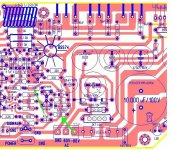
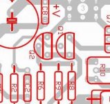
It seems that I don't see many TO-92 package having a triangular arrangement for their leads. We have to spread the leads from its factory release stage to meet assembling convenience. The C and E are moving out but does it really matters if the B is moving to the front (the print surface) or to the the back (the semi circular surface)? It might seem a bit strange in appearance though. And godfrey, the tripod arrangement do have some significance. See pict from one of my recent PCBs. If you have the 3 pads in line for Q2, you can never have that trace from R2 sneaking thru BC of Q2 and go to Q1 which is all "surrounded". This is most common arrangements in pcb software libraries, isn't ?
Like I said, I am not rushing anyone to order, in fact I like to go carefully and don't want to make reckless mistakes.
Alex, can you introduce some voids along the power traces especially the output trace which look awefully slim. Would it be a good idea to use 2 of the pads on the left of the 4 pole connector as the "In" and 2 of the pads on the right for "Out" on the protection pcb. But of course, you would have to broaden and move some traces around. Hope that is not too much work. Since we are now going double side, do you think it would be too much work to thermally couple the BC546 and BC182 pairs ?
I think it is pretty common these days to have components ID on the PCB rather than their values. It would be a lot easier to track errors. You can have 3, 4, 5 300ks in a circuit but you would not have 2 R12s. So I would say it is better to have IDs rather than their actual values on the silkscreen. And when we want to discuss whatever problem with a certain element, it would be a lot easier to address them.
It seems that I don't see many TO-92 package having a triangular arrangement for their leads. We have to spread the leads from its factory release stage to meet assembling convenience. The C and E are moving out but does it really matters if the B is moving to the front (the print surface) or to the the back (the semi circular surface)? It might seem a bit strange in appearance though. And godfrey, the tripod arrangement do have some significance. See pict from one of my recent PCBs. If you have the 3 pads in line for Q2, you can never have that trace from R2 sneaking thru BC of Q2 and go to Q1 which is all "surrounded". This is most common arrangements in pcb software libraries, isn't ?
Like I said, I am not rushing anyone to order, in fact I like to go carefully and don't want to make reckless mistakes.
Alex, can you introduce some voids along the power traces especially the output trace which look awefully slim. Would it be a good idea to use 2 of the pads on the left of the 4 pole connector as the "In" and 2 of the pads on the right for "Out" on the protection pcb. But of course, you would have to broaden and move some traces around. Hope that is not too much work. Since we are now going double side, do you think it would be too much work to thermally couple the BC546 and BC182 pairs ?
Attachments
but look at the x & y values alongside the frequency. They do not correspond.That value moves with the position of the cursor on the screen, so you can point at an area of interest and measure the x and y coordinates.
It has nothing to do with -3dB point.
Please explain what the F X Y values are telling us?
Group Buy has been setup here :
http://www.diyaudio.com/forums/group-buys/175296-pcb-order-goldmun-clone.html#post2331264
http://www.diyaudio.com/forums/group-buys/175296-pcb-order-goldmun-clone.html#post2331264
My criteria for a good design is to apply minimum compensation to a completed design to achive your goal rather than applying a lot of compensation to an oscillator to achive the same ideal. Which is the better approach? Jam
Jam, I can completely understand your point of view. It's a "safe" viewpoint.
However, the stability issue brings to mind something I heard of years ago: when designing fighter aircraft, the shape of the airplane was once chosen to give the plane "stability" so that the pilot would always be able to keep it under control. Modern designs, however, do something different. They push it more into the "unstable" range. The advantage this gives is that the aircraft is more "willing" to move about, change direction, and results in a more "agile" maneuverability.
Perhaps the secret of the great sound of this amp could be seen as analogous to what makes a nimble fighter aircraft desirable? The amp is just "itching" to go somewhere?
???
Another thing to consider here , do you really want 120v AC to be on this amp's main board ??? Would not a separate voltage doubler/cap multiplier board be wiser and allow for DC only to reach the board ? One could construct this on the same board as the PCB mounted trafo. Just a thought , not a mod.
I guess , there are those who would "build first and design later"
OS
I guess , there are those who would "build first and design later"
OS
Last edited:
hi, i'm new here. this would be a "current feedback"
design, I take it. because you said it is the best you ever heard, and because it goes out to 1Mhz. Only the current feedback topology goes out to 1 Mhz. Mark Alexander, with a BSEE from U of T, who works for analog devices, invented this topology, and he published it on the internet. I see, that on ebay, there is a Chinese copy of the current feedback amplifier, available for 30$ per channel.
Do you think that ebay item is any good?
2 X DELUXE HI-FI CURRENT FEEDBACK POWER AMPLIFIER KIT! on eBay (end time 20-Oct-10 21:55:35 BST)
Jam, I can completely understand your point of view. It's a "safe" viewpoint.
Perhaps the secret of the great sound of this amp could be seen as analogous to what makes a nimble fighter aircraft desirable? The amp is just "itching" to go somewhere?
???
Like .... into the air.

Safety First!
uzernaam,
You bring up an intresting point but in this case I don't think it works well in our instance. Current fighter aircraft use huge amounts of computing power to keep them flying (lots of feedback) basicly a unstable system on the verge of destruction and control.
Applying this to audio circuits, lets see extreme amounts of feedback, sliding bias,heavy compensation..........you see where I am heading, been there tried that.
The idea here is to identify you goals, design a system to meet said goals build system and apply a minimum amount of compensation.
Some rules that I have learned along the way (open to debate)
a) Obtain the required bandwidth (audio) before the application of feedback.
b) Feedback is a subtractive process.....it has its uses but once something is lost.......
c) DC to light design is a double edged sword consider the loads you will be driving or are you tied to one pair of speaker cables and speakers.
Our goals here are way different from a fighter aircraft
Regards,
Jam
Last edited:
Nice reading : Spectral Audio DMA-180 High-Current Reference Amplifier
200W/ch, with the DIP8 version of the 2N556* dual JFET type at the input + Hitachi TO3's.
As do the DMA80, DMA90, DMA100 from 1982 and the DMA50 from 1984 ,Mr Demian Martin is a DMA designer and member of this club.
You gents are heading for a world of pain.
200W/ch, with the DIP8 version of the 2N556* dual JFET type at the input + Hitachi TO3's.
As do the DMA80, DMA90, DMA100 from 1982 and the DMA50 from 1984 ,Mr Demian Martin is a DMA designer and member of this club.
You gents are heading for a world of pain.
Attachments
Last edited:
Can anyone tell me where to get hold of those 2sk134, 2sj49 or 2sk135, 2sj50 mosfets, I see them on the schematics but they have long been discontinued. I would like to repair a channel on a amp of mine I built as a teenager and Ive tried about every other Lmosfet on the planet but none have the same sweet sound, Im stuck with a amp where their is a sound difference between the channels. This amp you have here will not sound even close to the original if you dont use the original output mosfets either.
You either buy them for $25 minimum each or at $5/pc in lots of 50 pairs.
(take a guess how many TO3 complementary MOSFETs i have, of which i'm not selling any btw)
From where pls, I think its worth the 25 bucks each, route, I need 3 pairs. I built this amp when I was 15, it has complementary input LTPs, complementary vas LTPs and a Lmosfet outputstage, I havent seen any design close to it on this forum or any other for that matter.
Jacco,
I wish we could get out hands on that Spectral schematic. It sounds sweet. One high dollar amplifier. Somewhat similar topology as the Goldmund. It even shows the input jfet sealed canister thing.
As old as some of the Goldmund components are there should be a generic or outsourced provider where they can be found for a more resonable sum of money. I mean Fairchild makes copies of IR mosfets which have better characteristics. I am looking anyone else. Spec's are spec's.
Tad
There are two 33K resistors in the schematic and both are needed. Why is this up for a debate? The original schematic is on page one for everyone to see. Please take a look at it.
The power supply should be on the main board as Alex has designed.
This PCB is 100% correct and extremely well designed, layed out.
The power supply should be on the main board as Alex has designed.
This PCB is 100% correct and extremely well designed, layed out.
QUOTE=homemodder
......... it has complementary input LTPs, complementary vas LTPs and a Lmosfet outputstage, I havent seen any design close to it on this forum or any other for that matter.
........i think the elektor crescendo amps look like your description,they used sk135/sj50..........
greets
......... it has complementary input LTPs, complementary vas LTPs and a Lmosfet outputstage, I havent seen any design close to it on this forum or any other for that matter.
........i think the elektor crescendo amps look like your description,they used sk135/sj50..........
greets
- Home
- Amplifiers
- Solid State
- The Very Best Amplifier I Have Ever Heard!!!!