QUOTE=homemodder
......... it has complementary input LTPs, complementary vas LTPs and a Lmosfet outputstage, I havent seen any design close to it on this forum or any other for that matter.
........i think the elektor crescendo amps look like your description,they used sk135/sj50..........
greets
Thats the only other amp Ive seen using this topology, I built this amp back in 1986, many years before the elektor and I recall it was a year or two old already, its one of the very best amps Ive ever heard, called KW-MOS250.
I assume you've likely never seen the K-Lang amp schematic ? (was published in the electronics mag Menno van der Veen wrote for here)
I'm not in an All-Santa mood right now, certainly not at this thread.
One decent trick to find parts, and anything else, is to google in different language settings (which i'm awfully good at, btw)
Frequently there's a real good deal here and/or there.
Like close to 200 TO3s for $1 each here : http://www.diyaudio.com/forums/swap-meet/121949-obsolete-transistors-2sk135-2sj50-3.html#post1566603 (not that i didn't already have any K135, magnatecs, or anything TOP3. )
)
Couple of months later i ran into a large stash of J50s for $5 each, by using the routine above, makes $6 the pair. (and nearly 100% same batch)
I'm not in an All-Santa mood right now, certainly not at this thread.
One decent trick to find parts, and anything else, is to google in different language settings (which i'm awfully good at, btw)
Frequently there's a real good deal here and/or there.
Like close to 200 TO3s for $1 each here : http://www.diyaudio.com/forums/swap-meet/121949-obsolete-transistors-2sk135-2sj50-3.html#post1566603 (not that i didn't already have any K135, magnatecs, or anything TOP3.
)Couple of months later i ran into a large stash of J50s for $5 each, by using the routine above, makes $6 the pair. (and nearly 100% same batch)
Last edited:
Thats the only other amp Ive seen using this topology, I built this amp back in 1986, many years before the elektor and I recall it was a year or two old already, its one of the very best amps Ive ever heard, called KW-MOS250.
Crescendo in its 2X140W version date from early 1984 if not 1983...
personally, i'd be A LOT more interested in conversation about the design and "cloning" of this spectral amp. even without seeing the schematic, the mechanical design and construction alone would be, as mr spock used to say, "fascinating".
")
mlloyd1
mlloyd1
Nice reading : Spectral Audio DMA-180 High-Current Reference Amplifier
...
You gents are heading for a world of pain.
This is turning into the relic thread.
www.albs.de
Press : Produkte
Press : MOS 100-300
(sorry to say i built just about all of them in AB and A, all SS or Hybrid.
Anything from 20 to 200W, 50KHz to 1MHz bandwidth, including the oldy Burbely DC100 with servo.)
Last call, i'm outahere.
www.albs.de
Press : Produkte
Press : MOS 100-300
(sorry to say i built just about all of them in AB and A, all SS or Hybrid.
Anything from 20 to 200W, 50KHz to 1MHz bandwidth, including the oldy Burbely DC100 with servo.)
Last call, i'm outahere.
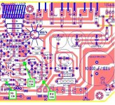
There is an extra 33K resistor on the PCB. R13 has been duplicated. See pic below. The PCB is wrong.There are two 33K resistors in the schematic...
[snip]
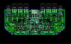
This PCB is 100% correct and extremely well designed, layed out.
Attachments
but look at the x & y values alongside the frequency. They do not correspond.
Please explain what the F X Y values are telling us?
They are telling us nothing except where the cursor is on the screen. You can't see the cursor because it is hidden.
The coordinates have nothing to do with the results.
I hope I have answered your question.
I can post another image so can see the cursor if you like.
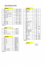
Well guys I observed the thread for some time and the project really seems to be nice, I might be interested in the boards as well, can someone please summarize the project as
type of amplifier, expected power, and put a parts list together? This might help to have in one reply as the complete informations, what might help as well might be a powersource design. Just to make a complete overview.
Regards,
Daniel
type of amplifier, expected power, and put a parts list together? This might help to have in one reply as the complete informations, what might help as well might be a powersource design. Just to make a complete overview.
Regards,
Daniel
- Home
- Amplifiers
- Solid State
- The Very Best Amplifier I Have Ever Heard!!!!