Thank you Sawyers, just find some unused TL072 and on Ltspice they looks very promising, so I will try and report back the result as soon as the filter is done...all the best to everybody
The TL072 was introduced in 1977 - so it is a 43 year old design. Amazingly, being such a useful design with decent specs it is commonly available from every manufacturer now (any TI patent on this device having long expired).
It is a bit on the noisy side, depending on application. As Marcel has pointed out if you want a more recent FET input device the OPA2134 takes some beating, as does the even more recent and superb OPA1656 (there is a thread in Vendors on this site by the designer of this device). For a bipolar the LM4562 is excellent, and is better in most regards than the NE5332, but not by much.
But if you build it using turned pin opamp sockets, you can try out different opamps easily. Some of the above (like the OPA1656) are only surface mount, so you'd need a SM/DIL adaptor (eBay) if you want to try that out in an 8-pin DIL socket. And practice the skill of soldering surface mount devices.
Whether you will *hear* the difference between different excellent performance op-amps is debateable - when the 072 does 0.003% and the LM4562 does 0.00003%, really who would hear the additional number of zeros?
Last edited:
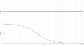
For completeness, here are the graphs for my figure 4. I didn't bother plotting the response for left and right in phase with equal magnitude, as it is the same old almost 0 dB and 0 degrees graph.
The response for left and right in antiphase is a nice fourth-order Butterworth high-pass.
Unfortunately, the response of figure 4 with one channel driven and the other silent looks absolutely horrible. There is a big notch, a bump in the transfer to the other channel and the channel separation only reaches 30 dB around 1.5 kHz.
Attachments
Last edited:
The TL072 was introduced in 1977 - so it is a 43 year old design. Amazingly, being such a useful design with decent specs it is commonly available from every manufacturer now (any TI patent on this device having long expired).
It is a bit on the noisy side, depending on application. As Marcel has pointed out if you want a more recent FET input device the OPA2134 takes some beating, as does the even more recent and superb OPA1656 (there is a thread in Vendors on this site by the designer of this device). For a bipolar the LM4562 is excellent, and is better in most regards than the NE5332, but not by much.
But if you build it using turned pin opamp sockets, you can try out different opamps easily. Some of the above (like the OPA1656) are only surface mount, so you'd need a SM/DIL adaptor (eBay) if you want to try that out in an 8-pin DIL socket. And practice the skill of soldering surface mount devices.
Whether you will *hear* the difference between different excellent performance op-amps is debateable - when the 072 does 0.003% and the LM4562 does 0.00003%, really who would hear the additional number of zeros?
Thank you so much very helpful information....all the best
Hi Monty78pig,
Have you had a look at Douglas Self's book "Electronics for Vinyl"? Chapter 12 deals with Subsonic Filtering and presents lots of discussion and options.
My attempts use an 18Hz 8th-order HPF (1 quad opamp) for each channel to attenuate everything that is not music followed by splitting the spectrum of each channel at 150Hz using 4th order Linkwitz-Riley filters to eliminate the verical rumble. The LR filters have the nice property of not creating a notch if you sum the HP and LP parts of the spectrum (which is what happens when you sum 2nd order filters).
I'm not sure how the KAB USA RF1 works but they really do seem to know what they are doing.
When I was a kid we had an old wind-up record player and a little cup of needles. We never threw the old needles out but every so often would change the needle(!). It is no wonder that a lot of 78s sound so bad - the grooves may be completely chewed up and whatever music there may have been is ground away.
Using Linkwitz-Riley filters is a nice and original way to do it. It has the same disadvantage as the Devinyliser: an all-pass response for in-phase signals, so a relatively poor phase response. Then again, that may be a smaller disadvantage than those of the alternatives I came up with.
Hi Marcel,
The "rumble" we hear comes from several sources: bad turntable bearings, pinch wheel eccentricity, off center hole in the disc, record warps, tone-arm resonances, and of course, the rumble that was put into the record during manufacture. I have some AAD CDs where you can hear the analog imperfections. And, of course, those cheap CDs that someone made from vinyl. I'm not really sure how many of those "rumble-like" signals can be eliminated or usefully attenuated just by electronic filtering. The 18 Hz HPF does seem to clear up most of the subsonic rumble. The "mono-ing" of the LF signal does appear to eliminate the out-of-phase vertical rumble without creating noticeable "phase-funnies". I do however, have some LPs where the recording engineer created a psudo stereo by putting most of the bass in one channel and parts of the treble (including the vocals) in the other. Mono-ing would obviously mess this up. Have you ever tried listening to a noisy disc with your preamp switched out of stereo into mono? On some discs this makes quite an improvement allowing one to concentrate on the music instead of having to listening to the noise. Luckily, my decks and arms are quite good and most of my LPs are quite good. Surface noise, scratches, and clicks and pops seem more objectionable than rumble!
Can you post a circuit for your working De-Rumble-iser?
Best Regards,
Tubewaller
Phono Derumbler
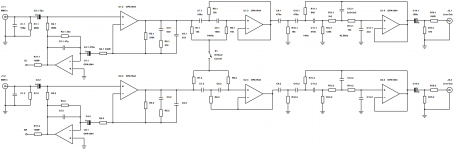
The Linkwitz-Riley Phono Derumbler is shown in the attached circuit diagram. There are basically 8 blocks: left and right channel buffers (the LR filters have low input impedances that can interact unless buffered), a summing amplifier (labeled LEFT + RIGHT MIXER), two high pass filters (one for the left channel and one for the right), a low pass filter for "mono" center channel, and a pair of summing amps to mix the left and right high pass filtered signal with the center low pass filtered signal.
What is seen is that there is no hump or notch in either of the reconstituted left and right channels. This is a a feature of the 4th order LR filters that have been used in professional active filter crossovers for years (see RANE, for example).
An excellent resource can be found at Rod Elliott's website (Elliott Sound Products). Rod has a calculator for the filter component values.
The LR filters are actually cascaded 2nd order filters (in this case Butterworth). Douglas Self calls them MCP (for Multiple Critical Poles) filters. Claude Lindquist referred to them as "sync-tuned" filters. They do have an advantage of a simple 4th order Butterworth in that the "Q" for both stages is 0.7071 - they are both critically damped which reduces the sensitivity to component tolerances. BUT, the main reason for using the LR filters is that the phases of the LPF and HPF at the crossover point have both been shifted 360 degrees, in other words, no weird humps, dips, or notches.
I've been using eSketch as my Spice circuit design tool for years. Unfortunately, the Canadian gentleman who developed it may have retired because it is no longer actively supported. But, you can still find it on the web.
Hopefully, the schematic will be clear enough for you enthusiasts out there to enter it into your favorite simulators to see if it actually works the way I think it does.
Attachments
Normalized responses, if I calculated them correctly:
L = R: second-order all-pass response with Q = 1/2 sqrt(2)
L = -R: fourth-order Linkwitz-Riley high-pass
Left channel driven, right silent:
Left to left:
(s^4 + 1/2)/(s^2 + sqrt(2) s + 1)^2, magnitude (omega^4 + 1/2)/(omega^4 + 1), which increases monotonically from 1/2 to 1
Left to right:
Fourth-order Linkwitz-Riley low-pass with gain of 1/2 at DC.
You are right: no bumps or troughs, channel separation that increases at a fourth-order asymptotic rate above the cut-off frequency, rumble suppression that increases at a fourth-order asymptotic rate below the cut-off frequency, the only disadvantage is the all-pass response for L = R.
Phono Derumbler
Hi Marcel, Thank you for the quick response and analysis.
I'll test the circuit with a triangle wave to see if what comes out looks peculiar.
The question of "phase distortion" has been written about but seem to recall that it is innocuous (references?). There was a discussion about the importance or otherwise about output polarity. I reasoned that it did matter for transients (like a cymbal crash) if the speaker cone pushed air into the room with a forward cone movement or created a rarefaction transient by moving in towards the speaker cabinet. It should be easy enough to try out....
BTW: Are you named after the HV generator?
No, my family name is Van de Gevel rather than Van de Graaff. A gevel is the front of a house, so I guess one of my ancestors lived in a house with a remarkable front when Napoleon decided that everyone needed to get a family name.
Phase distortion indeed has to be pretty bad to become audible, especially on music in a reverberant room. Still, it would be nice to avoid it - but I can't think of any way to avoid it without introducing some other artefact.
Phase distortion indeed has to be pretty bad to become audible, especially on music in a reverberant room. Still, it would be nice to avoid it - but I can't think of any way to avoid it without introducing some other artefact.
Phono Derumbler
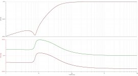
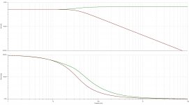
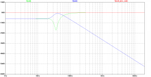
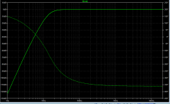
Attached are a couple of frequency response curves for the Derumbler first with the RIGHT CHANNEL GROUNDED and secondly with the RIGHT CHANNEL INVERTED.
Look at the RIGHT CHANNEL GROUNDED plot. Below 150Hz, the output from the LEFT CHANNEL is 6dB down because the right channel is a zero. Above 150Hz the LEFT output rises to 0dB.
Now look at the RIGHT CHANNEL INVERTED. Below 100Hz, both outputs fall at 80dB/decade. Above 300Hz, the response is flat. This is because the Linkwitz-Riley filters can't give the sharp corner that you'd get from a 4th order Butterworth.
I didn't bother with the situation in which both LEFT and RIGHT channels are working correctly because it is a flat line at 0dB with no bumps, dips, or notches.
The circuit previously shown uses 75nF and 150nF caps. I have a good supply of 150nF polypropylene caps but not 75nF and it seems like a waste of money and space to series connect two 150nF caps to make a 75nf.
A better solution is to use 47nF for the lower value cap and to parallel a couple of them to make the higher valued cap. The appropriate value for the resistors is 16K for the lower value resistors and to use a couple of 16K in series for the higher value resistor.
Attachments
I built the derumbler over the past couple of days. In order to test it I had to add a circuit that adds rumble. It includes a switch so that the rumble can be inverted on one channel (to simulate vertical rumble) or in phase on both left and right channels (to simulate lateral rumble).
The good news is that the circuit does appear to work. With the conditioning board simulating vertical rumble, both channels are derumbled. As expected, the circuit does nothing for lateral (in phase) rumble. I've built an 18 Hz 8th order Butterworth high pass filter that is 40 dB down at 10 Hz that should be good for vented box subwoofers.
The output amplitude remains level (as eyeballed on my scope). The thing that most notably varies is the phase of the output compared to the input. I will verify if what I actually see agrees with all the simulations.
One interesting thing with the Linkwitz-Riley high- and low-pass filters is the amplitude and phase at the "cut-off" frequencies. With a 4th order Butterworth, the amplitude at cut-off would be 0.7071 (i.e. - 3dB). The 4th order LR is actually a pair of identical 2nd order Butterworths tuned to the same cut-off frequency, therefore the amplitude is 0.7071 squared, in other words 0.5.
Watch this space over the next few days for test results and screen shots.
I've built several "anti rumble" "anti feedback" filters from Rod Elliot's Project 99 design, all with excellent results.
Project 99 - Subsonic Filter
As far as I can tell, these don't audibly affect the music at all, and the lack of woofer-robbing pumping and wasted amplifier power from that leaves more for the amplifiers to send lovely music to my ears.
By the way, it doesn't matter if you think your system is devoid of rumble, etc., because it does have the ability to produce sub-sonic frequencies.
Even pristine vinyl records have built-in subsonic noise.
A gentle warp, even invisible to the eye, contains subsonic energy.
And who needs that?
I've built several "anti rumble" "anti feedback" filters from Rod Elliot's Project 99 design, all with excellent results.
Project 99 - Subsonic Filter
As far as I can tell, these don't audibly affect the music at all, and the lack of woofer-robbing pumping and wasted amplifier power from that leaves more for the amplifiers to send lovely music to my ears.
By the way, it doesn't matter if you think your system is devoid of rumble, etc., because it does have the ability to produce sub-sonic frequencies.
Even pristine vinyl records have built-in subsonic noise.
A gentle warp, even invisible to the eye, contains subsonic energy.
And who needs that?
Thank you so much wiseoldtech for point out this rumble filter, I make a simulation and look so far one of the best in response......all the best
Attachments
Hi Wiseoldtech and Kissabout2002,
Rod Elliott's website (ESP) is full of proven circuits (and he has PCBs!). You might also like to look at Douglas Self's book "Electronics for Vinyl" that also has just about everything you need to know about phono preamps. The section of rumble filters is very comprehensive.
For the past 2 years I've used an 8th order Butterworth high pass filter whose caps are all 100nF. The resistors are all parallel pairs of E24 resistors that come out closer that 0.1% E96 resistors (Doug Self pointed this out in his book). The corner frequency is 18Hz and the response is down 40dB at 10 Hz. I notice from the graph that the attenuation is only about 20dB at 10 Hz, Apparently, the worst part of cartridge/ arm resonance occurs in the 10-12 Hz region so I tried a compromise that loses as little of the 20Hz plus but attenuates as much as possible in the 10-12Hz region. Doug Self provides a very thorough analysis of filter orders and types (even elliptic filters).
As they say in the Old Country, "The proof of the pudding is in the eating". If you find a circuit that works for you and it doesn't create objectionable "funnies" then go for it. Some people go nuts over the lowest noise - I don't ever listen to music with my ear pressed up against the speaker - it ruins the soundstage! I prefer the most accurate RIAA response in my phono preamps.
My testing is on pause because neither of my USB DSOs work properly with Win 10. Luckily my pair of Tektronix 214 Storage Scopes are still working brilliantly (not the NiCad battery packs which have been retired). I should get my 4-channel DSO on Sunday and so should be able to produce traces a bit more professional-looking than snaps of a phosphor screen by my phone!
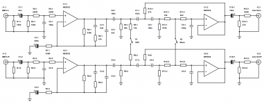
Here are a couple of more recent implementations of full phonostages that incorporate vertical filters that I have realised.
The first circuit is a simplified version that uses a single stage filter with a first order, switchable differential vertical rumble filter built into a third order subsonic filter at 18Hz.
The second circuit is a bit more complicated and uses an ultra low noise RIAA stage that mitigates the effect of noise from the loading resistor as the cartridge impedance increases with frequency. The vertical filter is implemented through a second order differential Bessel filter set to 140Hz. The usual 3rd order subsonic filter follows.
Gain for both stages is a healthy 40dB ! With low frequency noise diminished with can realise another 6dB more headroom in the preamp than we might otherwise be able to.
Subsonic rumble is especially harmful to bass reflex setups where the driver becomes progressively more unloaded as frequency drops below the tuning frequency. You can imagine a loudspeakers 'headroom', similar to a power amplifiers voltage rail limit, as the linear excursion. The loudspeaker quickly runs out of this 'headroom' or excursion as frequency decreases and inaudible rumble can cause significant fluttery distortion and potentially up to 20dB of lost effective headroom. I am currently working on a rather interesting 6th order bass reflex alignment that uses an electronic second order filter with a Q factor of 2 tuned half an octave below the usual optimal cutoff to lower the tuning frequency and remove any low frequency that could result in excessive excursion.
Although the circuit at the beginning of the article does work, the differential filter topology is far more efficient.
The first circuit is a simplified version that uses a single stage filter with a first order, switchable differential vertical rumble filter built into a third order subsonic filter at 18Hz.
The second circuit is a bit more complicated and uses an ultra low noise RIAA stage that mitigates the effect of noise from the loading resistor as the cartridge impedance increases with frequency. The vertical filter is implemented through a second order differential Bessel filter set to 140Hz. The usual 3rd order subsonic filter follows.
Gain for both stages is a healthy 40dB
! With low frequency noise diminished with can realise another 6dB more headroom in the preamp than we might otherwise be able to.Subsonic rumble is especially harmful to bass reflex setups where the driver becomes progressively more unloaded as frequency drops below the tuning frequency. You can imagine a loudspeakers 'headroom', similar to a power amplifiers voltage rail limit, as the linear excursion. The loudspeaker quickly runs out of this 'headroom' or excursion as frequency decreases and inaudible rumble can cause significant fluttery distortion and potentially up to 20dB of lost effective headroom. I am currently working on a rather interesting 6th order bass reflex alignment that uses an electronic second order filter with a Q factor of 2 tuned half an octave below the usual optimal cutoff to lower the tuning frequency and remove any low frequency that could result in excessive excursion.
Although the circuit at the beginning of the article does work, the differential filter topology is far more efficient.
Attachments
Thanks Monty. Both of the circuits look very interesting.
My phono stage starts with a X20 non-inverting amp. This drives the unity gain inverter that connects to the bottom end of the input loading 47K via two 470K resistors in series. I put a switch that can ground the bottom end of the 47K (idea courtesy of Doug Self) so that you can listen to the effect of the "electronic cooling" or "load synthesis". The higher frequencies of the input noise are attenuated by the following LPF action of the RIAA de-emphasis so that the front end noise is more like pink noise rather than white. It is definitely different from broad-band hiss.
Years ago I read an article in Electronics Today International by Stan Curtis (who was Doug Self's boss at some stage) about using an input buffer followed by an inverting RIAA filter. The disadvantage is the noise contribution by the input resistor of the inverter. The advantage is that the "virtual earth" eliminates the need for the final RC that that is tagged onto the end of the non-inverting RIAA amps. I like the split inverting design (75us stage DC gain = -10, followed by the 3180/318us shelving circuit DC gain = -10) first of all because it cuts down interactions compared to the "all in one go" non-inverters AND I feel that it sounds "smoother". Also, the overall DC gain of +2000 is perfect for amplifying moving magnet carts with 5mV output at 1 KHz to the 1 volt level. I typically keep the feed-in resistors at 1K which really doesn't do too much harm to the SNR.
Incidentally, I do have capacitance loading switches (4 position DIP switch with 22pF, 47pf, 100pF, 100pf) that I use in conjunction with low-capacitance cable. Adjusting the loading capacitance for a moving magnet cartridge can produce an extended frequency response (nothing like as good as a moving coil). However, the frequency response is not all that flat. That is where I use a 31-channel graphic equalizer in the FX loop that is quite good at leveling the response using a pink noise generator that I designed based on a book by Solomon Golomb called Shift Register Sequences. "HiFi" people are usually horrified at the thought of a graphic equalizer but sound recording and mixing engineers use GEs and compressors, especially for non-classical music.
What is your music setup?
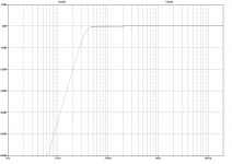
With Rod Elliots topology, faster rolloff is possible using alternate part values, at the expense of 50% more group delay at 20Hz (37mS vs 23mS).
Adjusted to be the same 2dB down @ 20Hz as Elliots. Much better in the 8-12dB range. This graph optimized with 85nF caps, a non-standard film value. Purple trace uses Rod Elliots values, Green trace is with alternate values:

Similar results can be obtained using standard 82nF & 91nF caps (Elliots values in Yellow):

Adjusted to be the same 2dB down @ 20Hz as Elliots. Much better in the 8-12dB range. This graph optimized with 85nF caps, a non-standard film value. Purple trace uses Rod Elliots values, Green trace is with alternate values:
Similar results can be obtained using standard 82nF & 91nF caps (Elliots values in Yellow):
- Status
- This old topic is closed. If you want to reopen this topic, contact a moderator using the "Report Post" button.
- Home
- Source & Line
- Analogue Source
- The ultimate rumble filter - far more effective than just a high pass filter!