Excellent. Thanks Charlie.
I have the CAD drawing you sent me, but a few questions:
(I'm going to use your picture for visual)
1) Is the jig frame extending vertically above the wire surface the exact width of lattice?
2) Do tensioning bolts just tighten to yellow pine?
3) What did you use to weld jack bolt to plate?
4) Do you think with a width of ~15" the MDF would need bracing to keep flat?
5) Do you place the 11 tpi thread rod during wire stretch?
Enough questions for now, thanks again.
Cheers
-Steve
I have the CAD drawing you sent me, but a few questions:
(I'm going to use your picture for visual)
An externally hosted image should be here but it was not working when we last tested it.
1) Is the jig frame extending vertically above the wire surface the exact width of lattice?
2) Do tensioning bolts just tighten to yellow pine?
3) What did you use to weld jack bolt to plate?
4) Do you think with a width of ~15" the MDF would need bracing to keep flat?
5) Do you place the 11 tpi thread rod during wire stretch?
Enough questions for now, thanks again.
Cheers
-Steve
Your questions:
1) Is the jig frame extending vertically above the wire surface the exact width of lattice?
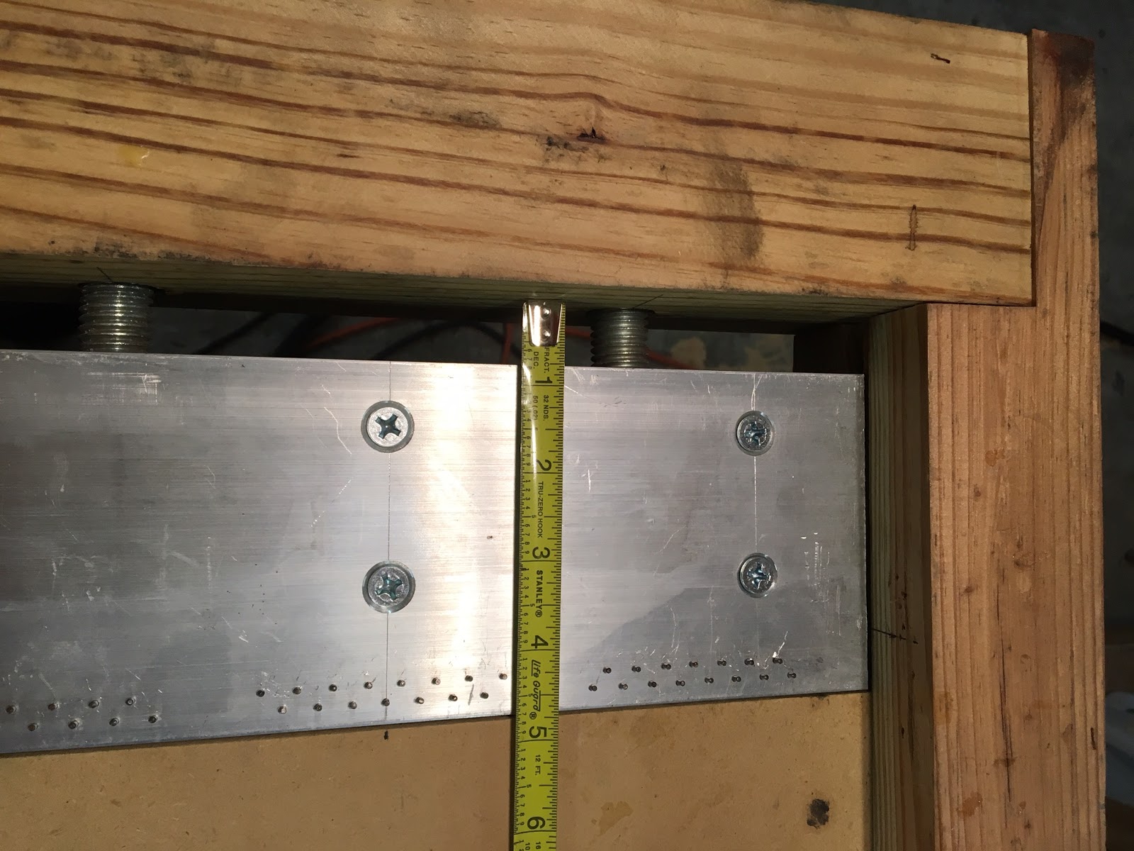
I don't quite follow this question. From my perspective the lattice is 12" wide and the jig frame extends vertically 1.44" above the jig platform. Thus; subtracting the .052 wire diameter, the jig frame extends 1.39" above the plane of the wires' surface.
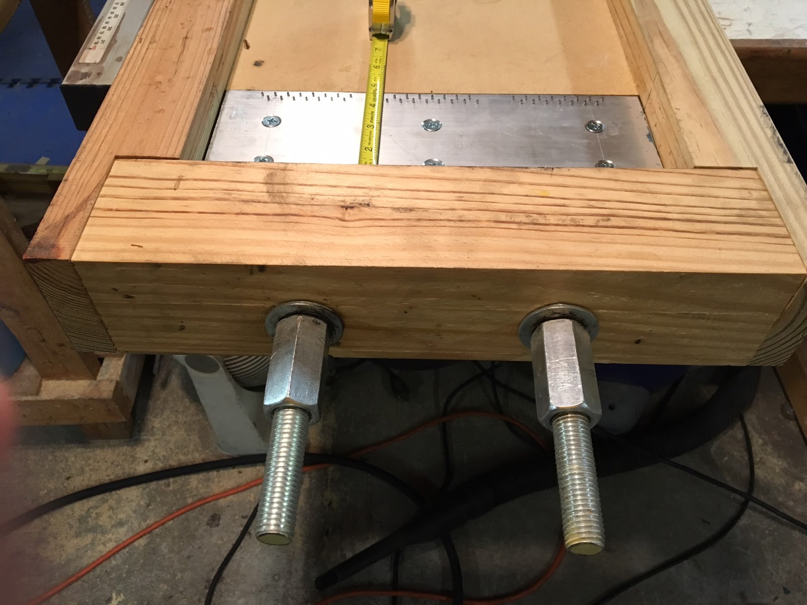
2) Do tensioning bolts just tighten to yellow pine?
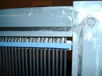
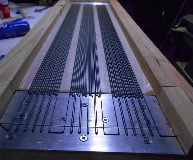
See the photo: Turning the (2) coupling nuts on the 3/4 all thread jack rods pulls the movable pin plate toward the pine end rail to stretch the wires. The movable pin plate has .75" of travel which is sufficient to stretch my stators' wire loops from 46.75" un-stretched length to their 48" stretched length. For taller panels you would need to increase the jig's length and travel proportionally.
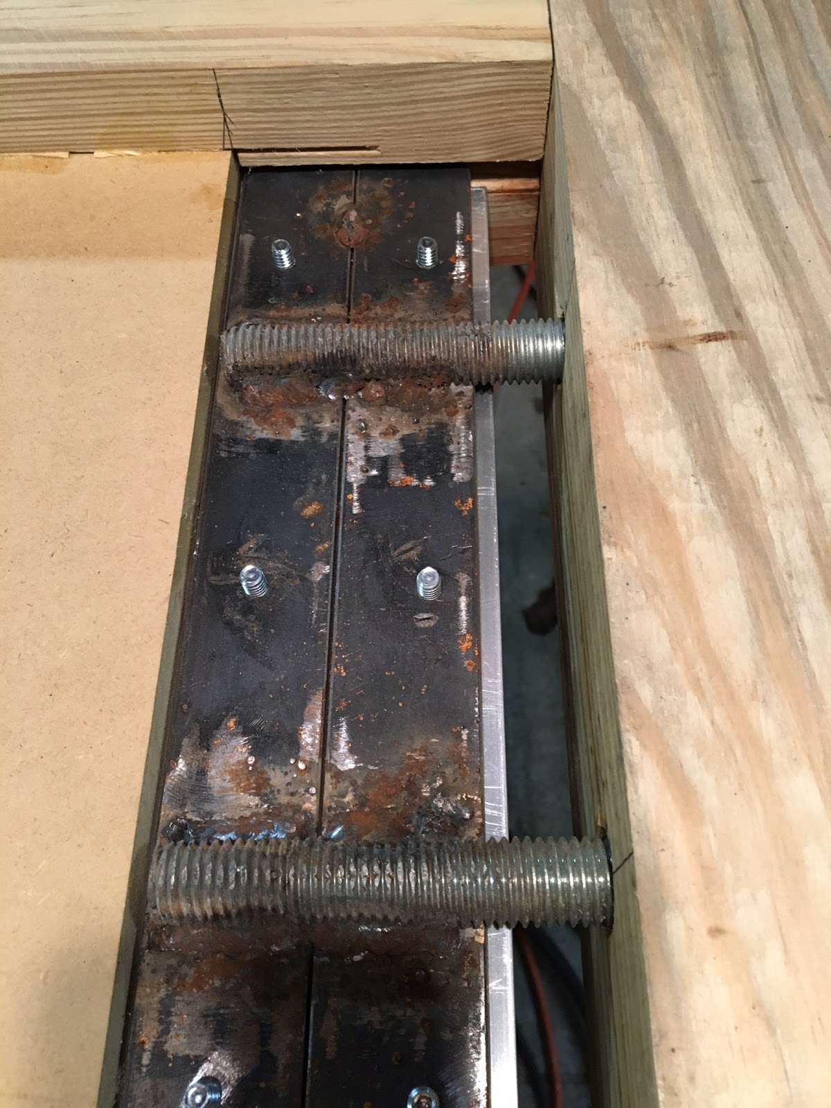
3) What did you use to weld jack bolt to plate?
See the photo. You can't weld aluminum to steel so there are steel sub plates welded to the jack bolt rods and the aluminum pin plates bolts to the steel sub plate. I used 1/4 steel for this but I've since re-drawn my CAD drawing to use a 3/16" thick steel sub plate from McMaster Carr. Note also that I ground flat surfaces on all thread rods where they contact the steel jack plate. I ground away 1/4" of the rods diameter to make the flats... the purpose being to minimize the offset between the rods' centerline and the wires (so as to pull the wires approximately in line with the rods).
4) Do you think with a width of ~15" the MDF would need bracing to keep flat?
No
5) Do you place the 11 tpi thread rod during wire stretch?
No; only after the wires are stretched and then relaxed. I relaxed practically all of the tension on the wires prior to gluing so as not to preload and warp the stator. The 11 tpi rods are used as comb guides to maintain proper wire spacing.
1) Is the jig frame extending vertically above the wire surface the exact width of lattice?
I don't quite follow this question. From my perspective the lattice is 12" wide and the jig frame extends vertically 1.44" above the jig platform. Thus; subtracting the .052 wire diameter, the jig frame extends 1.39" above the plane of the wires' surface.
2) Do tensioning bolts just tighten to yellow pine?
See the photo: Turning the (2) coupling nuts on the 3/4 all thread jack rods pulls the movable pin plate toward the pine end rail to stretch the wires. The movable pin plate has .75" of travel which is sufficient to stretch my stators' wire loops from 46.75" un-stretched length to their 48" stretched length. For taller panels you would need to increase the jig's length and travel proportionally.
3) What did you use to weld jack bolt to plate?
See the photo. You can't weld aluminum to steel so there are steel sub plates welded to the jack bolt rods and the aluminum pin plates bolts to the steel sub plate. I used 1/4 steel for this but I've since re-drawn my CAD drawing to use a 3/16" thick steel sub plate from McMaster Carr. Note also that I ground flat surfaces on all thread rods where they contact the steel jack plate. I ground away 1/4" of the rods diameter to make the flats... the purpose being to minimize the offset between the rods' centerline and the wires (so as to pull the wires approximately in line with the rods).
4) Do you think with a width of ~15" the MDF would need bracing to keep flat?
No
5) Do you place the 11 tpi thread rod during wire stretch?
No; only after the wires are stretched and then relaxed. I relaxed practically all of the tension on the wires prior to gluing so as not to preload and warp the stator. The 11 tpi rods are used as comb guides to maintain proper wire spacing.
Last edited:
Thanks Charlie for the explanations, and the pics helped a ton..")
Regarding Q1, I was just wondering if you made the width of the jig so that the lattice fits and centers (side to side), without having to do it by eye.
Regarding the welding: MIG? TIG? ..good old fashioned torch using brazing rods?
(believe it or not I still have my Dad's old torches and rods..lol..)
So my machinist friend calls back and says water-jet machining is way cheaper and cleaner than CNC, I had never heard of such a thing, so I looked it up, amazing.
(probably old news for a lot of folks though)
He doesn't have access, so without friend's ($) help, still probably cheaper going wire.
But for anyone else thinking of going PCB, they can go any depth desired, which would mean no extra CNC step and no etching to dial back the Cu.
Just for fun: https://www.youtube.com/watch?v=4FSPFUSs2BM#t=337.013326
Last time I ordered wire from them(a few years ago), it was about $50/1000ft roll.Tried in vain to get a quote for wire by the weekend, no dice. I figure I need around 3700 feet (some spare) for this build, what does that amount of wire cost going on past experience? (rough estimate is fine)
Copper cost has been steadily increasing, so it will likely be a bit more than that.
@ bolserst: They still have not sent me a quote, but yea, looked up 1000ft on the bay and it's 75usd now, oh well.
To clarify, the reason I asked about the jig width, is I'd like to make one that could do an 18" panel, even though this one will only be 15".
I think I'll do that and just oversize the lattice until fastened, then cut off excess later, I'd really like to have the capacity/option of making a bigger panel in the future.
@ Charlie: Speaking of the jig again, one more question:
Is the reason you used 2 Al plates on the one end for different tensions on the lead wires? If so, could you explain the 'how' or point me to an explanation?
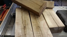
Finally, speaking of the lattice, I forgot that the local Amish gave me a bunch of Maple (which I love) that I could use for it's construction. I can get a ton more if needed, it's all aged/dried too. Any reason I shouldn't use it?
Of course if I do use it, it'll be lots of squaring, planing and sanding, (+omitting splits etc.) but the price was right..
Pic:
To clarify, the reason I asked about the jig width, is I'd like to make one that could do an 18" panel, even though this one will only be 15".
I think I'll do that and just oversize the lattice until fastened, then cut off excess later, I'd really like to have the capacity/option of making a bigger panel in the future.
@ Charlie: Speaking of the jig again, one more question:
Is the reason you used 2 Al plates on the one end for different tensions on the lead wires? If so, could you explain the 'how' or point me to an explanation?
Finally, speaking of the lattice, I forgot that the local Amish gave me a bunch of Maple (which I love) that I could use for it's construction. I can get a ton more if needed, it's all aged/dried too. Any reason I shouldn't use it?
Of course if I do use it, it'll be lots of squaring, planing and sanding, (+omitting splits etc.) but the price was right..
Pic:
Attachments
Last edited:
Thanks Charlie for the explanations, and the pics helped a ton..
Regarding Q1, I was just wondering if you made the width of the jig so that the lattice fits and centers (side to side), without having to do it by eye.
Regarding the welding: MIG? TIG? ..good old fashioned torch using brazing rods?
(believe it or not I still have my Dad's old torches and rods..lol..)
So my machinist friend calls back and says water-jet machining is way cheaper and cleaner than CNC, I had never heard of such a thing, so I looked it up, amazing.
(probably old news for a lot of folks though)
He doesn't have access, so without friend's ($) help, still probably cheaper going wire.
But for anyone else thinking of going PCB, they can go any depth desired, which would mean no extra CNC step and no etching to dial back the Cu.
Just for fun: https://www.youtube.com/watch?v=4FSPFUSs2BM#t=337.013326
As I recall the jig opening is exactly 12 inches wide but I made the lattice about 1/32" narrower to facilitate removal after gluing. Basically I just folded a sheet of notebook paper and inserted it between the lattice side rails and jig to provide clearance.
The lattice details are notched to interlock together so the center support rails and horizontal slats lock in at correct locations. I used a right angle square to square the vertical rails into the jig, and then the horizontal slats drop into the notches and glue down over the wires.
As for welding the sub plate to the jack bolt rods, I just used an old Lincoln stick welder, nothing fancy. The heat warped the plate some but a little hammer work brought it back reasonably flat again.
After building the jig I changed the CAD design to simplify construction-- on the jig I built the sub plate rides in guide slots cut into the jig frame but on the revised CAD drawing I moved the guide slot and made the pin plate wider so now the pin plate itself rides in the guide slots.
@ Charlie: Speaking of the jig again, one more question:
Is the reason you used 2 Al plates on the one end for different tensions on the lead wires? If so, could you explain the 'how' or point me to an explanation?
Finally, speaking of the lattice, I forgot that the local Amish gave me a bunch of Maple (which I love) that I could use for it's construction. I can get a ton more if needed, it's all aged/dried too. Any reason I shouldn't use it?
Of course if I do use it, it'll be lots of squaring, planing and sanding, (+omitting splits etc.) but the price was right..
Pic:
I needed a 6" wide pin plate at one end in order to extend the length of those wire loops that would become the leads that connect to the network resistors. McMaster Carr didn't have a 6" wide x 3/16 thick plate so I purchased 2" and 4" widths to make the 6" I needed.
I think maple would be a good choice for the wonderful for the lattice details. 1/4" A-A plywood would be the most dimensionally stable but it certainly wouldn't have the esthetics of maple.
As a woodworker I can tell you that wood warps when you cut it; depending on the amount of dried-in stress that it has. Therefore, NEVER rip a board to net width in one pass. Rather, you have to sneak up on straightness in multiple passes.
I use rough sawn hardwood a lot. A planar won't plane a warped or twisted board to flatness. First you must cut one face flat using a jointer, and then cut the opposite face flat and parallel using a planar.
Also, whenever you feed a board through a planar, don't shoot for net thickness in one pass but use multiple passes removing a small amount on each pass and eyeball the board for warp after each pass. If you see a warp developing, flip the board over and plane the convex face-- the board will then start warping back toward straight/flat condition.
This is why I say that when cutting hardwood, you have to sneak up on flatness and straightness using multiple passes through the cutter.
BTW if you opt for an 18" wide jig, and intend to use 3/16" pin plates (much cheaper) you might need to add a third jack rod to spread the pulling force.
Judging from the rather significant torque I had to apply to the jack nuts on my jig to stretch 90 wires at once for one stator, I can only imagine a jig configured to stretch wires for two stators at once would be REALLY prone to bending and self destructing-- another reason I'm glad I didn't go that route.
Last edited:
OK Great, all questions answered, thanks much.
I figured on another jack bolt, yea, that's gonna be a LOT of pressure.
Matter of fact I'll be modifying a few parts of the jig quite a bit to accommodate my particular build, but your plans are a great reference..
The aluminum plate will be 1/4" instead of 3/16" due to my machinist having a bunch on hand, so I'll need to widen the dada a skosh, plus I'll get one the full 6" for 'B'.
The revised plan having the plate itself in the slots is smart, I'm gonna round the front edge of the moving plate just slightly ...I'm thinking the extra pressure will be under control.
May go with a bit longer pins too and drill almost completely through the plate for more holding power, my depth guide on the DP will come in handy for that.
As for the woodworking tips, I agree on all points, I learned from an old pro who followed very similar guidelines when I was working with him.
(shame he's unable to do so anymore)
Haven't veered away from that ol' kraut's way of doing things, and for good reason..
Out to the shop to get some work done, think I've chatted enough..haha..
Good luck with trying to get a price quote from Jaguar industries.Well, I just got an e-mail from Interstate Wire, they checked with 3 different suppliers, and cannot obtain the wire I was after...
Here: WIA-2001-0 - UL AWM Style 1429 | Interstate Wire
This is the wire that Charlie recommended, also I believe the same that bengal used.
Does anyone have another type of wire to recommend? ..when I google the type Calvin posted, I mostly get sites from across the pond, no idea there..
What is it about this specific wire? I seem to remember something about the PVC being cross-linked, IDK?
I'm not sure, I'm afraid..hmmm..
Help?
 I’m still waiting for responses to three requests that I’ve sent them last year. I ended up buying wire for my test panel from Remington industries on ebay. I paid $56 including shipping for 1000 ft of 24 gage wire. It was the cheapest wire I could find. It is rated for 300V but I did not have problems biasing it at 6KV. You have to be careful with the size. According to their spec overall D=0.054” but the spool that I got had D= 0.052”
Here is the link to their store. remington_industries on eBay.
It is not difficult to build wire stators and the only downfall is that the design is not very robust as they can be easily damaged. Although I started with perfectly straight wires after I stretched them, I ended up accidently bending them in a few spots when I was gluing them to the lattice. I’ve been thinking about PCB stators for my final build. I believe that 36X 48” sheet costs around $150 locally. I don’t have an access to CNC router so the cost of farming it out is likely prohibitive.
Cheers,
Alex
Yikes.... I paid about $25 for a 1000 feet at Interstate wire.
Yikes indeed! More than double, no, triple now...Looks like Bengel and I bought up the last of the cheap wire from Interstate.
And Charlie's right, according to the sales gal at Interstate, they have not purchased quantities of that particular wire since 2004 (!!)
That would explain the huge difference in cost/price compared to now..
Also means I'm going to get a quote for water-jet machining some PCB panels just to set my mind at ease before ordering the wire.
Plus inquiring about shipping cost from Mainland China via Alibaba.
And yes, I have checked and made sure I am able to purchase as an individual, just need to use my name as the 'company' name.
(face it, all they really want is your money/good-for-the-money credit card)
Wish me luck...
Oh, and if golfnut reads this post, how did you 'connect' your upper and lower panels? ... both electrically and physically. Thanks in advance..
(hope I'm remembering my info correctly)
Last edited:
Hi
The stator sections (front and back with membrane and copper-tape ring to charge the membrane) in my ESLs are bolted together using nylon screws. The copper tape is laid over a recessed countersink screw - which is how I make the connection to the HT
Each section is then bolted to the aluminium frame., also using nylon screws.
The lower section is connected to the transformer at the bottom of the section via two wires, and to the upper section with two short (20 mm) flying leads. You can daisy chain as many stator sections as you want that way. I've also daisy-chained the HT connection in a similar manner- the lower section has two countersink screws connected to the tape.
Hi,
here are some suggestions from my early days panels
First I used Nylon screws also, with the threads cut into the PVC spacer frame.
Found that it had no edge over simple taping everything together, but was a pita for servicing.
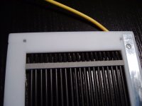
Second pic shows the connection and kind of contact ring.
I used graphite spray as charge ring and a simple screw for external connection.
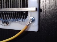
Similar solution in pic 3 and 4 with the difference that the charge ring was made from thin slices of household aluminum foil ... certainly cheaper and easier to source than copper strips ... and functions equally well.
jauu
Calvin
here are some suggestions from my early days panels
First I used Nylon screws also, with the threads cut into the PVC spacer frame.
Found that it had no edge over simple taping everything together, but was a pita for servicing.
Second pic shows the connection and kind of contact ring.
I used graphite spray as charge ring and a simple screw for external connection.
Similar solution in pic 3 and 4 with the difference that the charge ring was made from thin slices of household aluminum foil ... certainly cheaper and easier to source than copper strips ... and functions equally well.
jauu
Calvin
Attachments
Looks like Bengel and I bought up the last of the cheap wire from Interstate.
I contacted them, and they have it in stock... but it is $.036/foot now.
This is the stuff I used....
WIA-2001-0 - UL AWM Style 1429 | Interstate Wire
I contacted them, and they have it in stock... but it is $.036/foot now.
This is the stuff I used....
WIA-2001-0 - UL AWM Style 1429 | Interstate Wire
Hey that's a good price! I think Wreck needs about 3,000ft which would be only $108
Thanks for getting back to me and reaching out to Interstate, bengel, much appreciated..
I talked to Lisa B, and she seemed quite upset that someone claimed out-of-stock/2004 on that particular wire, and wanted to know who told me that.
(don't remember who it was, so...)
Anyway, done deal. They had 4k ft. and I took all of it, just in case I want to make mine ~18"W instead of 15.
So it's back to constructing the wire-stretching jig, and mylar-stretching table for my 'final answer'. Sheez...I feel like I've been on the playground see-saw too long...no sense in looking back now though..haha..
Speaking of construction:
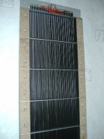
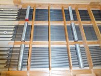
@Charlie: How many 5/8" threaded rods were required to space the wire before adhesion? In the picture I see two sets of three.
Looks like you have a set about every 7-9"...did you have additional sets every 7-9" going up the whole panel, or did you just move them as you went along? Thanks in advance..
Also, thanks Rod & Calvin for you explanations and pictures, all helpful..
I talked to Lisa B, and she seemed quite upset that someone claimed out-of-stock/2004 on that particular wire, and wanted to know who told me that.
(don't remember who it was, so...)
Anyway, done deal. They had 4k ft. and I took all of it, just in case I want to make mine ~18"W instead of 15.
So it's back to constructing the wire-stretching jig, and mylar-stretching table for my 'final answer'. Sheez...I feel like I've been on the playground see-saw too long...no sense in looking back now though..haha..
Speaking of construction:
@Charlie: How many 5/8" threaded rods were required to space the wire before adhesion? In the picture I see two sets of three.
Looks like you have a set about every 7-9"...did you have additional sets every 7-9" going up the whole panel, or did you just move them as you went along? Thanks in advance..
Also, thanks Rod & Calvin for you explanations and pictures, all helpful..
Attachments
Good news on the wire, Wreck. I don't suppose they will be getting anymore at that low price again.
About your question:
As you can see my stators are sectioned as 3 groups of 30 wires separated by 2 vertical center rails for the diaphragm support spacers. The horizontal wire support slats are on 2.5" centers. When assembling and gluing in the horizontal slats, I positioned the threaded rods just far enough apart to allow installing 3 slats between them-- installed them one at a time and then placed weights across the slats until the glue set. I actually had 3 additional threaded rod pieces (not shown in the above photo) with which I then assembled 3 more slats and applied weights over those too, until the glue set. If I had more threaded rods and plenty of small weights I could have continued without stopping. As it was, I was content to do six slats at a time and let the glue dry for at least an hour before continuing. I used various items for weights, including quart paint cans full of water. I let each stator set overnight before taking it out of the jig, though.
- Status
- This old topic is closed. If you want to reopen this topic, contact a moderator using the "Report Post" button.
- Home
- Loudspeakers
- Planars & Exotics
- The Thrill is Gone.. S-ESL Build