Thanks bolserst, good stuff, and provides a nice backdrop to evolved findings.
I've been down with respiratory ailments as of late, but am finally getting back to this project, so your posts are most welcome,(well, they always are") )
)
My step-up ratio is 152:1, and my amp is the Emotiva XPA-5, utilizing 2 channels for ESL duties.
Each channel is rated at 200w@8ohms, and 350w@4 if you feel like running sims/tests, no pressure though... (not sure what amp "level" I'll be running, FYI)
@ Calvin,
I really tried to defy your recommendations of the Dayton 7" by using the 8", ..ha!
Unless my ears are deceiving me though, the 7" in an open baffle has a much 'quicker' sound to it (especially stopping), and the 8", with it's heavier Mms, rings ...with no load otherwise provided by an enclosure.
I'm still going to run some tests with Praxis and REW, but just by listening, I think you're correct.
I've been down with respiratory ailments as of late, but am finally getting back to this project, so your posts are most welcome,(well, they always are
)My step-up ratio is 152:1, and my amp is the Emotiva XPA-5, utilizing 2 channels for ESL duties.
Each channel is rated at 200w@8ohms, and 350w@4 if you feel like running sims/tests, no pressure though...
(not sure what amp "level" I'll be running, FYI)@ Calvin,
I really tried to defy your recommendations of the Dayton 7" by using the 8", ..ha!
Unless my ears are deceiving me though, the 7" in an open baffle has a much 'quicker' sound to it (especially stopping), and the 8", with it's heavier Mms, rings ...with no load otherwise provided by an enclosure.
I'm still going to run some tests with Praxis and REW, but just by listening, I think you're correct.
Last edited:
That's the info I needed.... if you feel like running sims/tests, no pressure though...

I'll get the worst case RMS power/voltage requirements for your segmentation resistors posted up later this week.
Haha...thanks Calvin, yes, you were right to begin with ...alter-ego or no..
I ended up ordering 12 (6 per side) of the Dayton Reference 7 inch drivers.
I do have questions about the bass tower(s) though.
I see that you use a bit of side panels in your designs, and I plan on doing that.
How much distance provides the most benefit, without adversely affecting dipole effect?
Is there some article I should read, or some acoustic theory I should understand before I make a decision?
I also see that you use the same width for the front of the baffle...
Would baffle diffraction be decreased if I used an angled baffle?
Say, 12 inches at the bottom down to 7 inches at the top? Or doesn't it matter at these low frequencies?
Thanks a bunch guys...
Cheers -Steve
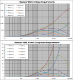
Find attached the worst case RMS power and voltage requirements for your ESL design.My step-up ratio is 152:1, and my amp is the Emotiva XPA-5, utilizing 2 channels for ESL duties. Each channel is rated at 200w@8ohms, and 350w@4 if you feel like running sims/tests
As mentioned previously, when playing music rather than high-level test tones, average power dissipation is usually 1/10 or less of the values shown. The important thing is to abide by the voltage rating by using HV rated resistors, or putting 2 or 3 in series to achieve the same result.
Some light bedtime reading on the subject of U-frame dipole woofers....How much distance provides the most benefit, without adversely affecting dipole effect? Is there some article I should read, or some acoustic theory I should understand before I make a decision?
DIY-dipole-1
http://www.quarter-wave.com/OBs/U_and_H_Frames.pdf
Longer sides increases LF output, but get them too long and the cavity resonance starts encroaching on the passband. A few experiments/measurements with different sized "wings" should get you to the sweet spot while avoiding the math
Not sure if you had seen it, but Calvin provided some information on his dipole woofer tower in another thread. What I gathered from his comments was that he selected the A-frame arrangement and dimensions for aesthetic reasons, but was able to achieve similar performance to an H-frame.
http://www.diyaudio.com/forums/plan...suitable-x-over-frequency-10.html#post2291092
Attachments
Thanks bolserst and Calvin, again, guidance much appreciated..
More info has lead to more questions:
1) How important is the distance between the dipole tower and the ESL?
If it's too far away, will comb filtering result?
If it's too close, will sonic interference result?
Note: I'm not necessarily talking about mylar collapsing into stators, but general 'spillover' from the DP tower into the panel.
Is there some sort of consensus on an optimal distance?
Note Two: I've looked at setup guides for ML Statement e2, I'm thinking about copying this design, good idea or bad? here: https://www.martinlogan.com/pdf/manuals/manual_statement_e2.pdf
2) Given the stated measurements of holes drilled into the aluminum on the jig, and the precision involved, would anyone recommend having it done by a machine shop? (speaking of Charlie's jig drawings here)
Or, as long as the threaded rod can be employed without force to align the wires, is 'close enough' acceptable?
Side note: I understand that different distances need to be drilled at opposite ends of the jig due to looping the wire around and back, but you would agree that 91 thousandth of an inch is a bit difficult to measure/mark, no?
Bottom line: Will 'close enough' starting from the center out, work?
3) Will the Mylar from late 2013 still be good to use? (been stored away from UV, heat, and humidity) The 3m tapes? (same storage)
Enough for now,
-Steve
Hi Steve,
I can speak to your questions #2 & #3:
2) The pin plates in my jig were drilled using a cheap Harbor Freight Tools bench top drill press and I placed a wooden 4-degree wedge under the aluminum plate in order to tilt the holes 4 degrees from vertical.
As you can see in my drawing the hole locations are dimensioned relative to a scribed centerline on the aluminum plate. I started by positioning the plate with the centerline centered under the drill bit and then used the depth gauge on my vernier caliper to shift the plate to the first hole location. For example: If the first hole was (let's say) .100" to the left of the plate centerline, I used the caliper to shift the plate .100" left and then drilled the first hole. I had a bank stop setup to keep the plate from shifting fore-to-aft-- all I had to do then was shift the plate side-to-side to the hole locations.
Since you will be using threaded rod to realign the wires for gluing, accuracy is not so important for the hole locations. You must however, stagger the holes as shown on my drawing.
3) The Mylar you referred to will work fine-- The Mylar in my latest speaker was left over from the roll I purchased for another speaker built 8 years earlier.
Last edited:
Thanks much Charlie, that's a big relief to hear..
Didn't mean to come off negative, I was just 'having a day'..haha..like we all do from time to time..
Cool, I've got my wedge all set to go, just need to rig up a jig for stability and I should be all set..
Also, I know I need a horizontal lattice brace every 3".. but I wonder how few vertical braces for an 18" span... think I could get away with two? Or do I need three or more?
I don't recall seeing that requirement posted anywhere...
I know I need a horizontal lattice brace every 3".. but I wonder how few vertical braces for an 18" span... think I could get away with two? Or do I need three or more?
I don't recall seeing that requirement posted anywhere...
Roger Sanders' 70-100 x d/s rule applies-- so if you are building a hybrid panel of 18" width and the d/s (diaphragm-to-stator spacing) is .063, then the maximum span between supports must not exceed 100 x .063 or 6.3", which means you could get away with two vertical spacers dividing the diaphragm into three sections. Three vertical spacers would be the more conservative approach in terms of supporting the diaphragm. However, having a spacer in the center of the panel may complicate the segmentation and wouldn't be as esthetically pleasing. I would favor using two vertical spacers and reducing the width of the panel a bit so as not to push the limits of Sanders' 70-100 rule.
Last edited:

- Status
- This old topic is closed. If you want to reopen this topic, contact a moderator using the "Report Post" button.
- Home
- Loudspeakers
- Planars & Exotics
- The Thrill is Gone.. S-ESL Build