Now really tight (as p2p goes).
PS: Does anyone know this supplier ? outillage.e44.com
E44-Eurocard motif centronix/sub-d - 100x160mm - fr4 (1pc/bl) à 5,00 ?[productImages]/0/
PS: Does anyone know this supplier ? outillage.e44.com
E44-Eurocard motif centronix/sub-d - 100x160mm - fr4 (1pc/bl) à 5,00 ?[productImages]/0/
Attachments
Hello there
Im noob here
Please advice....
Im currently building a CMoy with salas shunt reg for PSU
I've got the board from CRT ( thank to him )
But when i done soldering, it didnt worked well....
Im using transformer 50vac, 2x15v
And im using MSR860 diode, resistor 10R 5 watt
I only got 9.7v from V-
But V+ is zero....
Please advice....
No, I am not right.
I am asking Salas, where should the cap C3 be?
Nearest to the Mosfet depending on how much heat is being dissipated. If its a high dissipation setting better compromise distance.
But when i done soldering, it didnt worked well....
Im using transformer 50vac, 2x15v
And im using MSR860 diode, resistor 10R 5 watt
I only got 9.7v from V-
But V+ is zero....
Please advice....
I see a bunch of voltage reference leds not emitting. See if you got one or more of them wrongly orientated or dead from too hot an iron or long soldering. If your meter can light an led in diode mode just test them one by one with same and correct in circuit polarity without removing them first. If meter can't, use a 9V battery fast.
Need Information Please
Dear Salas,
I want to build your shunt regulator with this schematic for +5V output for my DAC
I use PCM1798 and CS8416.
Can this regulator maintain +5V on its output as PCM1798 and CS8416 greatly vary in current requirement as the sampling frequency change?
For 44.1KHz, PCM1798 require about 25mA, CS8416 require about 14.5mA.
For 192Khz, PCM1798 require about 45mA, CS8416 require about 40.5mA.
I usually play different sampling rate music files with my DAC.
Best Regards
Dear Salas,
I want to build your shunt regulator with this schematic for +5V output for my DAC
An externally hosted image should be here but it was not working when we last tested it.
I use PCM1798 and CS8416.
Can this regulator maintain +5V on its output as PCM1798 and CS8416 greatly vary in current requirement as the sampling frequency change?
For 44.1KHz, PCM1798 require about 25mA, CS8416 require about 14.5mA.
For 192Khz, PCM1798 require about 45mA, CS8416 require about 40.5mA.
I usually play different sampling rate music files with my DAC.
Best Regards
True, i was actually thinking to use smd versions of the resistors and the leds, and indeed leave the rest in peace.
Just wondering if anyone succeeded so far, and see what pitfalls there are in layouting
I actually find smd more pleasant to work with than trough hole as well
Just wondering if anyone succeeded so far, and see what pitfalls there are in layouting
I actually find smd more pleasant to work with than trough hole as well
This must have been asked before, but i cant find it (not at least in a way that i understand).
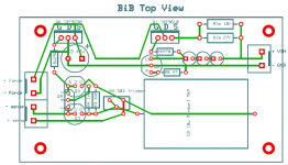
Can somebody explain the function of the zobel network at the output of the 1.2bib? What happens if i use different capacitor values (i now use 220uf + 3.3uf, where 4.7-10uf is recommended).
Thanks!
Can somebody explain the function of the zobel network at the output of the 1.2bib? What happens if i use different capacitor values (i now use 220uf + 3.3uf, where 4.7-10uf is recommended).
Thanks!
- Status
- This old topic is closed. If you want to reopen this topic, contact a moderator using the "Report Post" button.
- Home
- Amplifiers
- Power Supplies
- The simplistic Salas low voltage shunt regulator