Sorry the information is for SSLV1.1 BiB shunt regulator. Could you post or link your schematic?
For BiB the manual said: "A fully resistive choice can have smoother and lower noise spectrum to
filter and lends for C102,202,302 MKT. 4.7uF-10uF. 10uF filters better. Electrolytic 220uF is
even more efficient a filter for sensitive digital and MC phono stages"
For BiB the manual said: "A fully resistive choice can have smoother and lower noise spectrum to
filter and lends for C102,202,302 MKT. 4.7uF-10uF. 10uF filters better. Electrolytic 220uF is
even more efficient a filter for sensitive digital and MC phono stages"
Last edited:
Hi all, still new to this forum, and have had a quick look at thread - but certainly haven't had time to read all of it. But looking at the circuit way back in Post #8 - looks elegant, but my question is - will it be able to supply 5.25 volts for my Buffalo 3 DAC? Seems to me that if Vgs on the IRG9240 (M2) is around 3.5 volts (which I expect - but I could be wrong) then there's only 1.75 volts left for Q2 - will Vce of 1.75V be enough for effective operation of Q2? Also, how hard is it to get a precise 5.25V output - this circuit doesn't appear to be adjustable.
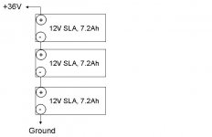
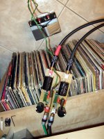
Also, I noticed that the original purpose of this circuit was a p-s for an RIAA stage - hmmm. Here is the schematic for my RIAA power supply. Now that is what I call simplistic! Does anyone really think that the simple shunt regulator sounds better than a battery?
Also, I noticed that the original purpose of this circuit was a p-s for an RIAA stage - hmmm. Here is the schematic for my RIAA power supply. Now that is what I call simplistic! Does anyone really think that the simple shunt regulator sounds better than a battery?
Attachments
I'm confused...
So what is recommended for output zobel for a dac supply and clock?
220-1000uF for Vref filtering and 4.7u-5.6u + 1R for the Zobel termination. If you got any noises in the rails you may add 47-100uF across sense terminals.
Hi all, still new to this forum, and have had a quick look at thread - but certainly haven't had time to read all of it. But looking at the circuit way back in Post #8 - looks elegant, but my question is - will it be able to supply 5.25 volts for my Buffalo 3 DAC? Seems to me that if Vgs on the IRG9240 (M2) is around 3.5 volts (which I expect - but I could be wrong) then there's only 1.75 volts left for Q2 - will Vce of 1.75V be enough for effective operation of Q2? Also, how hard is it to get a precise 5.25V output - this circuit doesn't appear to be adjustable.
Also, I noticed that the original purpose of this circuit was a p-s for an RIAA stage - hmmm. Here is the schematic for my RIAA power supply. Now that is what I call simplistic! Does anyone really think that the simple shunt regulator sounds better than a battery?
Margins are enough. Maybe you talk J2, because Q2 sees Vgs across it. J2 is low pinch off and its OK. See the SSLV1.1 (Bib) instructions. Shows application and adjustment for a range of needs. And its evolved in quality. I preferred it from a battery in the phono originally.
Attachments
For the voltage reference filter (C101 etc.), not for termination zobel.
You are right my mistake
 only jumper Rx07 when used lytic for Cx03
BiB the manual said: "A fully resistive choice can have smoother and lower noise spectrum to filter and lends for C102,202,302 MKT. 4.7uF-10uF. 10uF filters better. Electrolytic 220uF is
even more efficient a filter for sensitive digital and MC phono stages"
What would be a reason to put a lytic in c103?
What would be a reason to put a lytic in c103?
Instability and/or noise with a load that throws the phase margin that the reg can handle off.
Salas thanks for reply but now I am confused. I looks to me that J2 will actually see Vgs of IRF9240 M2. The source of J2 connects to gate of M2, and the drain of J2 connects to the source of M2 - doesn't it? Looks to me that Q2 is connected between the drain and the gate of M2.Margins are enough. Maybe you talk J2, because Q2 sees Vgs across it. J2 is low pinch off and its OK. See the SSLV1.1 (Bib) instructions. Shows application and adjustment for a range of needs. And its evolved in quality. I preferred it from a battery in the phono originally.
Sorry to bother you because I'm sure that there is a link somewhere in the thread, can you please direct me to SSLV instructions?
Thanks, Paul
Yes the opposite, I looked at it hastily. I have some using NMOS the other way around for HV and confused it. Still its working fine down to 5V mark, many made 5V MOS examples, and there is a BJT output version described for there about and lower. Look at V1.1 builds thread it has instructions in post one.
Thanks for the update Salas. have downloaded instructions and will read them on the train home. Regards, PaulYes the opposite, I looked at it hastily. I have some using NMOS the other way around for HV and confused it. Still its working fine down to 5V mark, many made 5V MOS examples, and there is a BJT output version described for there about and lower. Look at V1.1 builds thread it has instructions in post one.
What would be a reason to put a lytic in c103?
More protection against oscillation with incompatible loads, but less bandwidth.
I am gathering info to build a raw dc psu for my latest SSLV1 and need some clarification.
I want to use a 24V 80VA Tx to feed a 14Vout shunt.
I will use a RC filter after rectification.
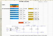
Using the SSLV1.1 spreadsheet (Fred's) for 24V Tx with 65ohm resistor and 200mA CCS I get 21Vdc (enough headroom for the 14Vout shunt).
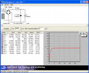
But when I input the same values into PSU Designer II, I get only ~~ 10Vout from the RC filter.
I know there is something wrong with my PSUDesigner simulation but what ?
And if the simulation is ok, than I do not know how to interpret the readings... some clarification is needed.... so as usual I hope someone cares to leave a coment.
I want to use a 24V 80VA Tx to feed a 14Vout shunt.
I will use a RC filter after rectification.
Using the SSLV1.1 spreadsheet (Fred's) for 24V Tx with 65ohm resistor and 200mA CCS I get 21Vdc (enough headroom for the 14Vout shunt).
But when I input the same values into PSU Designer II, I get only ~~ 10Vout from the RC filter.
I know there is something wrong with my PSUDesigner simulation but what ?
And if the simulation is ok, than I do not know how to interpret the readings... some clarification is needed.... so as usual I hope someone cares to leave a coment.
Attachments
- Status
- This old topic is closed. If you want to reopen this topic, contact a moderator using the "Report Post" button.
- Home
- Amplifiers
- Power Supplies
- The simplistic Salas low voltage shunt regulator