Hi Salas
Could you help me, please.
I'm building L'Amp, http://rothacher.typepad.com/files/lampccs.pdf CCS version, 35V-1,5A current...It's possible to use your Shunt regulated supply instead unregulated supply?
There is some problem with the CCs load, or i have to go direct into SIT?
I have red PCB, could advice about current setting and diodes and trsfos value.
Also, could use same shunt supply for negative bias?
I love your shunt, allmy system it's supply via Shunt!
Grazie mille
Marco
Salas
In this Article http://www.diyaudio.com/forums/diyaudio-com-articles/202480-l-amp-simple-sit-amp-part-deux.html
there is a voltage and current setting for the inductor load L'Amp
Ciao
In this Article http://www.diyaudio.com/forums/diyaudio-com-articles/202480-l-amp-simple-sit-amp-part-deux.html
there is a voltage and current setting for the inductor load L'Amp
Ciao
Its more about ambient temp it seems. Having the IRFs near the BCs and SKs says that. If the junctions aren't the cause and the case temps aren't 70C it wont give a damn.
yes, it seems like that as the majority of all components gets as hot as >50c. Even blue BCs show about 52 degrees. I know the design is not the best, but there was really no space in a tiny box I had (plss see att.)
")
By selecting R1 of 16ohms, there should be a current of about 150mA that is far enough for feeding preamp based only one LME49710HA per channel, isn't it?
Attachments
frankly speaking haven't compared 7812 & 7912 regs that are feeding DACs output opams (49710HAs as well, I like them) with shunt for preamp. However the 1st impression (CD-> trivial preamp on just 2x 49710HAs + shunt reg -> headphones) made me shocked, so damn good it was
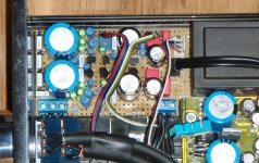
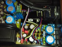
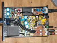
here is the overall picture of the overcrowded box (not finished yet, wires to 3.5mm socket will be replaced, pre and output RCAs for preamp will be added). I was thinking of replacing 7812 & 7912 as well with 2nd shunt reg, but seems that it would be simply impossible due to the lack of space and additional considerable heat.
here is the overall picture of the overcrowded box (not finished yet, wires to 3.5mm socket will be replaced, pre and output RCAs for preamp will be added). I was thinking of replacing 7812 & 7912 as well with 2nd shunt reg, but seems that it would be simply impossible due to the lack of space and additional considerable heat.
Attachments
Last edited:
Hi all,
just a quick word to say that the version of Reflektor given in post# 4797 seems to work ok on my bench.
Value used are strictly the one quoted on schematic. I did not managed to pair Ksa for the current mirror but used some from same batch and it seems to be ok. BC546 are B type, resistors are all low ppm (Vishay MRS or equivalent). 1000µf capacitor is 'regular' but 105°C, and 1uf is Vishay Mkt 1822.
It's 50v/ 50ma out (150 total current draw) with KSA1381 and BC546 as cascode ring for reference.
Slow start up behavior, it drift a little bit for nearly 10 minutes, then firm rock steady voltage out.
Prereg is 54V/0,5A transformer - standard bridge rectifier (KBL04) - 4700µf/100V - 47R/5W - 4700µf
I'll probably change the resistor for a bigger wattage one as it heat up a bit and is relatively close to capacitors.
No image for now sorry, but if you like i can later post the point to point template i used.
Salas: YOU ROCK!
Last edited:
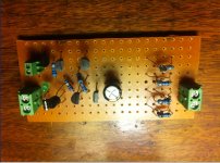
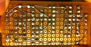
some pictures! (salas deserves lots of them )
first two is,for experimentation purpose, a modified version of sslv1.2 3.3V with a jfet instead of...r6? and 4 bf862 paralleled as the ccs. also the shunt mosfet is zvn0124a. the whole thing l fed by batteries. i did have some oscillations with no gate resistor for the bf862 but now it s fine. the jfet instead of r6 sounded not very natural so i eventually replaced it by the said resistor as per schematic, but the jfet ccs with batteries gave me transparency like never before. it s not even funny. i also tried it with the 1.1 and it works fine also.
build at your own risk though..... i used it to feed an es9022 for those interested.
if there is one thing i noticed out of trying different parts in this shunt reg is that low capacitance parts are of prime importance in sound quality for 3.3V in dacs.the SSLVV1.2 CCS also benefited from having a zvn3310a in another low current reg i made for clock. it s just too bad these are available in to-92 only...
on a more general note, i found out it is way more convenient to p2p on a larger pitch board like this one than a .1 inch board.
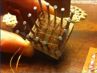
next, DIY resistor,
i used it in CRCRC... filter before SSLV1.1. it is made of 32ga copper magnet wire. for clock duty and i gain loads more detail and smoothness compared to MOX or even metal film. the thing is that it did not sound balanced. seems like digital supply dont like too much this kind resistor. maybe i ll try it later in something analog to see if it sounds more ''right'', or maybe the problem is the winding technique or even the concetpt itself...
i can show how i winded it if someone is interested(RCRUZ?).
oh i wish i had a scope as all this is purely subjective...
)first two is,for experimentation purpose, a modified version of sslv1.2 3.3V with a jfet instead of...r6? and 4 bf862 paralleled as the ccs. also the shunt mosfet is zvn0124a. the whole thing l fed by batteries. i did have some oscillations with no gate resistor for the bf862 but now it s fine. the jfet instead of r6 sounded not very natural so i eventually replaced it by the said resistor as per schematic, but the jfet ccs with batteries gave me transparency like never before. it s not even funny
. i also tried it with the 1.1 and it works fine also. build at your own risk though....
. i used it to feed an es9022 for those interested.if there is one thing i noticed out of trying different parts in this shunt reg is that low capacitance parts are of prime importance in sound quality for 3.3V in dacs.the SSLVV1.2 CCS also benefited from having a zvn3310a in another low current reg i made for clock. it s just too bad these are available in to-92 only...
on a more general note, i found out it is way more convenient to p2p on a larger pitch board like this one than a .1 inch board.
next, DIY resistor,
i used it in CRCRC... filter before SSLV1.1. it is made of 32ga copper magnet wire. for clock duty and i gain loads more detail and smoothness compared to MOX or even metal film. the thing is that it did not sound balanced. seems like digital supply dont like too much this kind resistor. maybe i ll try it later in something analog to see if it sounds more ''right'', or maybe the problem is the winding technique or even the concetpt itself...
i can show how i winded it if someone is interested(RCRUZ?
).oh i wish i had a scope as all this is purely subjective...
Attachments
Last edited:
The R6 for CCS substitution I had tried back in the inception days and I did not like it too. Low capacitance Jfets main CCS is great if making for low currents. Its just so much quiet and fast using high gm low noise parts. As for pre-filters, members always rated CLC high instead of CRC. If for resistor, they rated thick film high in DCB1 over MOX. Your findings ring valid in other words. Post a schematic with your parts of choice and settings for the low current TO-192 nice cute mini 1.2R if you may, there are many members who want for a clock, opamp etc. 
Now I am back after boxing up everything and I am also half way of ripping everything out of the boxes again I have a small issue, or a bigger one to be honest. On all the plus shunts I have 30mV AC out, I had to go to the store and get myself a cheapo oscilloscope to get it measured. I did hear it before and thought it was the cabling but it did not help to re-route or change to shielded.
I suppose this is a layout issue but for the sake of it I tried poking around with a small screwdriver on the pcb looking at the oscope at the same time. When I hit the leg of R9 connectected to Q7,Q8 It dropped to 1mV. This is the same on all 4.
First thought was to mount a 100k to 1M resistor to ground from there but I do not know what implications that would have or if it would even work. Do you have any suggestions. The Shunts are built according to 3rd schematisc in post #3200.
I have a small issue, or a bigger one to be honest. On all the plus shunts I have 30mV AC out, I had to go to the store and get myself a cheapo oscilloscope to get it measured. I did hear it before and thought it was the cabling but it did not help to re-route or change to shielded. I suppose this is a layout issue but for the sake of it I tried poking around with a small screwdriver on the pcb looking at the oscope at the same time. When I hit the leg of R9 connectected to Q7,Q8 It dropped to 1mV. This is the same on all 4.
First thought was to mount a 100k to 1M resistor to ground from there but I do not know what implications that would have or if it would even work. Do you have any suggestions. The Shunts are built according to 3rd schematisc in post #3200.
What's the difference between thick film, thin film, metal film and MOX when applied to resistors?
Which parameters cause the audible differences that are being reported?
Ed Simon had shown different very small scale distortion profiles between resistors, and there is PPM and inductance. Thin film are made by deposition where thick film are made by printing and different chemistry and the element is a thousand times fatter. Beyond that I haven't got a clue.
- Status
- This old topic is closed. If you want to reopen this topic, contact a moderator using the "Report Post" button.
- Home
- Amplifiers
- Power Supplies
- The simplistic Salas low voltage shunt regulator