The lower end of the C grade are already within the B grading limits.
Insert a notional 2V reference in there. What difference does that make?
What could be altered to correct that difference? Will the circuit benefit if that alteration is made. Maybe just swap the LEDs.
DIYaudio, the "it" refers to the learning part as well.
Insert a notional 2V reference in there. What difference does that make?
What could be altered to correct that difference? Will the circuit benefit if that alteration is made. Maybe just swap the LEDs.
DIYaudio, the "it" refers to the learning part as well.
Could I use BC560C grade instead BC560B?
Yes
Could I use LED 2V instead 1.8V?
Yes
")
I needed more current in the BIB I'd built on proto-board. Here's a table of alternate R101 values on the current limiter -- these are from simulations, but a quick two-point check proved them to be fairly acurate:
An externally hosted image should be here but it was not working when we last tested it.
Are you using the BIB's IRF9610 in CCS duty? Use 4 known ~2V Vf LEDS string for headroom, subtract the 9610's Vgs for your current target roughly from its specs sheet, and project a setting resistor ((VFx4)-(Vgs))/Rset. That's for going beyond 0.6A. Needing 300mA, 3 LEDS are OK plus they keep the resistor dissipation low. Getting near with the calc means you got the 9610 and 610 curves loaded already in it.
Attachments
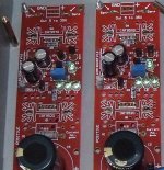
Hi, I've built two Quanghao boards for my Salas Phono, AC35V input for desired 40-45V output and I get 0V out with L4 not lighting up, L1-L3 are fine. Any ideas please?
If you will talk in circuit terms maybe I can help, bcs I am not familiar with the designations on those PCBs. Is L4 a sole LED in the Vout reference path? Maybe its inserted wrong polarity, or the JFET powering the ref system is dead. Are there any ''sense'' eyelets? If not sorted to the main lines on board or not extended to meet those at the load, the reference and error amp system are floating powerless.
Are you using the BIB's IRF9610 in CCS duty? Use 4 known ~2V Vf LEDS string for headroom, subtract the 9610's Vgs for your current target roughly from its specs sheet, and project a setting resistor ((VFx4)-(Vgs))/Rset. That's for going beyond 0.6A. Needing 300mA, 3 LEDS are OK plus they keep the resistor dissipation low. Getting near with the calc means you got the 9610 and 610 curves loaded already in it.
If memory serves correctly, the BIB board is provisioned for 3 green LEDs, not 4.
I needed more current in the BIB I'd built on proto-board.
You wrote you built on proto-board so if you need high current you can add a 4th easily I thought.
You wrote you built on proto-board so if you need high current you can add a 4th easily I thought.
but the BIB boards look so much nicer!!!
If you will talk in circuit terms maybe I can help, bcs I am not familiar with the designations on those PCBs. Is L4 a sole LED in the Vout reference path? Maybe its inserted wrong polarity, or the JFET powering the ref system is dead. Are there any ''sense'' eyelets? If not sorted to the main lines on board or not extended to meet those at the load, the reference and error amp system are floating powerless.
Hi, Yes the L4 LED is the single on in the Vout ref path. The sense links are shorted. It's a bit stange that they both have the same problem. Note Q1 and Q6 are mounted under the PCB's so the case is used as a heat-sink (mica pads used)
Attachments
They are OK with 3 LEDS for most uses. Vishay Mosfets show less Vgs even. Depends on batches. One stronger LED in the triplet can give headroom if Vgs is nearing when setting CCS high etc. What you will use it for? Will be symmetrical?
Yes, they will be symmetrical.
I had to select the LEDs -- the Vgs was too high with one batch.
While I'm on the 2nd GB list, seems that the board specifies K170 but the article uses K117 selected for 3 to 5mA Idss. I'm using K117 and IRF9610,IRF9530 per the article.
Hi, Yes the L4 LED is the single on in the Vout ref path. The sense links are shorted. It's a bit stange that they both have the same problem. Note Q1 and Q6 are mounted under the PCB's so the case is used as a heat-sink (mica pads used)
Check L4 for correct orientation. Are the 9540s oriented correctly for GDS? They need nylon washers too. No short of their tabs to chassis.
Thanks again Salas, I did indeed have a short to the casework. I have fixed that now, but realise I have used GR and not BL grade 2SK170's, and can't get the Vout as high as I will need it for my Low MC Simplistic phono (40-45V). One of the boards will produce 20V and the other 33V max. Do I need to change the vref, some of the Jfets or something else? I am waiting on some BL's for my phono section, but I built these reg boards some time ago.
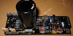
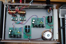
My latest contraption:
Double secondary winding TX - Double rectifiers - Two positive SSLV1, resulting in a +15v / 0 / -15v setup.
Successfully powering the buffers in my new preamp.
PS: As I had no Hexfred or Stealth diodes available, I used some ultra fast ones bypassed with smal wimas in the rectfier bridge.
The smoothers are nichicon and I use BG FK in the buffers PCB as decouling caps instead of the original regulators.
I believe major gains can be obtained by upgrading to SSLV12R and removing the FK.
Attachments
Last edited:
Salas,
For this circuit: Welborne Labs CATO Vacuumt Tube Linestage
1) How many low voltage regulator for each channel?
2) We need to source the power transformer for this project, to play safe, what is the AC voltage on secondary winding before feeding your low voltage regulator? How much drop from the regulator for +/-24V?
Thanks again!
- Status
- This old topic is closed. If you want to reopen this topic, contact a moderator using the "Report Post" button.
- Home
- Amplifiers
- Power Supplies
- The simplistic Salas low voltage shunt regulator