Yes, and I can't claim any precision down there. All I am saying is that when using this sound card in spectrum analyzer mode, with nothing connected to my setup, the noise sits at -90dB. I feed a 1kHz AC current, and then I see a 1kHz signal at -50dB or -60dB, and it changes according to how high the AC current is adjusted so that is repeatable. So I think that should be a measurement that works. No, I didnt calibrate it with a 0.23uV signal.
Actually, if I were to create a resistive divider with three resistors, the middle one being 600 Ohm, and the outer ones being 300K, and then take the "output" signal across the 600Ohm symmetrically, that would give me -60dB attenuation, and that could be used to check if the test system can resolve these levels or not. I would argue that if I use say a 1kHz sine wave as input signal, and see a 1kHz signal in the spectrum, the measurement is selective, and I am not just measuring noise. Would you agree?
I would agree. But you'd have to have a very precise amplitude in the sine wave. What's the accuracy of your true rms voltmeter in the amplitude range and frequency that your sine wave is.
I need to have -45Vout, what have I to change?
salas isn't around for a few days, you'll have to be patient.
")
swap the semiconductors for their complementary parts.
9610 >610
9240>240
bc550c > 560c
bc546c > 556c
Then turn around (invert) D1 & Q8 & Q9
swap C2 around.
swap the +ve & -ve power leads.
All the regulators can be changed in polarity by applying the same swapping rules.
The PCBs can be used for either polarity.
The -ve regs should be slightly cheaper, certainly the parts are more readily available.
There may be a slight increase in performance due to all N channel FETs being used.
salas isn't around for a few days, you'll have to be patient.
swap the semiconductors for their complementary parts.
9610 >610
9240>240
bc550c > 560c
bc546c > 556c
Then turn around (invert) D1 & Q8 & Q9
swap C2 around.
swap the +ve & -ve power leads.
All the regulators can be changed in polarity by applying the same swapping rules.
The PCBs can be used for either polarity.
The -ve regs should be slightly cheaper, certainly the parts are more readily available.
There may be a slight increase in performance due to all N channel FETs being used.
Thank you guys.
swap the semiconductors for their complementary parts.
9610 >610
9240>240
bc550c > 560c
bc546c > 556c
Then turn around (invert) D1 & Q8 & Q9
swap C2 around.
swap the +ve & -ve power leads.
All the regulators can be changed in polarity by applying the same swapping rules.
The PCBs can be used for either polarity.
The -ve regs should be slightly cheaper, certainly the parts are more readily available.
There may be a slight increase in performance due to all N channel FETs being used.
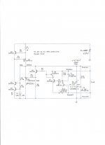
Like attached pic?
Attachments
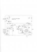
The shunt part can be used without any component changes, just switch the output and ground nodes, and use a negative CCS.
Iko, if this schematic is accurate, I think C1 and C4 would explain the strange rise in impedance. The MOSFET will have to sink large currents out of these caps before it can make any change at the feedback nodes.
http://www.ikosonic.com
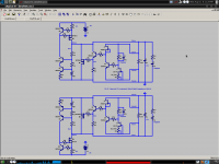
However I see this is absent on the second schematic.
- keantoken
Iko, if this schematic is accurate, I think C1 and C4 would explain the strange rise in impedance. The MOSFET will have to sink large currents out of these caps before it can make any change at the feedback nodes.
http://www.ikosonic.com
However I see this is absent on the second schematic.
- keantoken

sorry people... it's quite a long thread....i've got a buffalo III dac and i wish to use the salas shunt to power it, it needs 5-5.5vin, could you point me to a schematic with proper component values for this project?
thanks and all the best
Wich version?
if i knew i wouldn't ask seriously i don't know, i know there are many versions of this project, what interests me is one that is capable to feed the dac with a voltage of 5-5.5v @ 100-200mA, don't even know if is available something like that... i used with very good results the HV version so i wanted to try the LV with this new project.
thanks
seriously i don't know, i know there are many versions of this project, what interests me is one that is capable to feed the dac with a voltage of 5-5.5v @ 100-200mA, don't even know if is available something like that... i used with very good results the HV version so i wanted to try the LV with this new project.thanks
Last edited:
if i knew i wouldn't ask
thanks
I use this for BII, only change Vin-Vout 7-10V difference target Vout, R12 use 1K trimmer for 5.5Vout, you can get better perfomance using more current: I use ca. 500mA
Enjoy
P.S. AndrewT don't be so rude, the thread is too long.
Attachments
Last edited:
Hi Andrew
Reading a thread about pedja´s buffer, I read your post " even those that design and build discrete regulators sometimes use two positive regulators rather than design a + & - pair.
The only down side to this twin positive regulator is the requirement for dual secondaries and dual bridge rectifiers.
Most will accept the extra cost because of the technical benefit accruing from +ve regulators."
Do you also recommend the use of two positive Salas regs if we use separated secondary windings in the TX ?
Hi guys,
rebuilt another shunt reg (since the other guys are performing their duties in my phono stage) and measured again. This time I put 100uF caps across the LEDs for the current source and the norton ref for the voltage regulator.
First, the setup: I use a MOSFET biased in class A, with a source resistor of 1Ohm and an opamp to compare a DC voltage (coming from a 10 turn pot) to set the DC current, plus an AC voltage to overlay the AC current. This has a capacitor and source follower to couple the AC signal on the load input to a BNC socket.
THen, a soundcard (24bit, 192kHz) to look at the spectrum of that signal. I can reliably measure down to about -90dBu with this setup, not limited by the soundcard but limited by the noise in our lab and the whole construction. This is about 0.23uV.
(It actually works a little better, but there is a lot of 50Hz noise and its harmonics, plus some noise, so I want to be on the safe side). Sorry, no schematic, I have a hand-drawn, smeared piece of paper, this load is built from scrap box parts (maybe one day I'll find some time to properly document....)
Starting up the regulator with 16Vin, 12Vout, CCS set to 200mA, load current 100mA, the first positive surprise is that it is not adding any noise. I can't tell if it adds any noise because with my setup I couldnt detect it.
Then, I put a AC current of 27mA @ 1kHz on top, and the output spectrum showed a noise peak of -60dB == 0.8mV. Math gives 28mOhm. Some more work to do, more later.....
(BTW, shorting the diode in the emitter of the PNP yields 3dB improvement...)
Numbers are going down fast, from 120mOhm to 28 already. Now if you used a much higher hfe 560C instead of 2N4403 as error amp and a CCS instead of its resistor load plus 4 wires connection like we usually do, things could go even better? We just stick an LED between the ref resistor and its CCS for drift, the diode at the emitter worsens performance. Just Use a JFET that has <0.6V pinch off, and you won't need an extra silicon junction drop, vbe will suffice.
- Status
- This old topic is closed. If you want to reopen this topic, contact a moderator using the "Report Post" button.
- Home
- Amplifiers
- Power Supplies
- The simplistic Salas low voltage shunt regulator