Simulations are my weak side
IMHO we should first find corner frequency for 1/f noise. Our helping point is approx. 3nV@10Hz. 1/f noise will go up 3dB per octave if we plot toward lower frequencies.
I found some sn INTEGR directives that Keantoken had from the Yahoo LT Spice group (thanks). If I integrate 1Hz-120Hz it answers 11.214n (should be RMS). If I integrate 0.1Hz-120Hz it answers 54.233n.
*Moving the noise discussion to the main thread, it got a bit big and its OT in the build thread.
Attachments
Sure. It was a nice opportunity to learn more about noise integration in LT Spice though. Here is the Flea with same directives in the sim. I used analogous LT chip models. LT1028 ultra low noise and LT1086-12, hopping that they have some validity chances since they come with their own in-house simulator from the same company.
Attachments
As some of you know, I have been building salas shunts for a while now.
The first V1 versions where quite easy to implement and I actually etched some PCB´s for it.
Than came other versions like V12 (very difficult to implement P2P) and producing extremely good trebble resolution but IMO lacking some mid freq presence.
In the end I chose V12R as the best overall. This one can be built P2P but some care must be taken to avoid oscilations and startup issues.
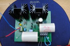
My last V12R builds (used in my new line pre-amp) represent the culmination of a long period of efforts. Although it uses inexpensive Vref and output MKP caps, it sounds wonderfull with very extended and detailed highs, a perfectly integrated mid section and powerfull detailed bass.
So I felt the urge to share and here it is:
The first V1 versions where quite easy to implement and I actually etched some PCB´s for it.
Than came other versions like V12 (very difficult to implement P2P) and producing extremely good trebble resolution but IMO lacking some mid freq presence.
In the end I chose V12R as the best overall. This one can be built P2P but some care must be taken to avoid oscilations and startup issues.
My last V12R builds (used in my new line pre-amp) represent the culmination of a long period of efforts. Although it uses inexpensive Vref and output MKP caps, it sounds wonderfull with very extended and detailed highs, a perfectly integrated mid section and powerfull detailed bass.
So I felt the urge to share and here it is:
Attachments
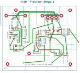
Some important hints:
Mosfet gate stoppers should be very close to the mosfets and carbon films work better eliminating startup issues. R2 should not be too close to R3.
Input GND should be connected directly to IRF9140 Drain.
A good quality resistor should be used for Vref.
Vref caps (M-Cap MKP 10u in this case) are determinant in the final tone / resolution so a Amp Ohm 10u or an Obbligato produce even better results.
The output cap (M-Cap MKP 4u7 in this case) can be bypassed by a quality SM or Teflon small value that clearly leave it´s signature there.
Nice layout p2p work Ricardo.
Thank you Salas
")
It would not have been possible without your input.
P.S. I have seen many asking what is the minimum drop across the regs from time to time. There are two axis. One is the minimum series drop, and the other is the DCin to ground minimum potential it takes to contain the CCS. In all regs of this family, the minimum series drop is what needs be on R1. On 1.2 and 1.2R its one Vbe. I.e. 0.61-0.65V. On 1 and 1.1 its whatever gets developed across R1. Can be 2V with 10 Ohm at 200mA for instance. From DCin to ground for 1.2-1.2R BJT CCS tail, its one Vgs, 3x Vbe and 1x Vf. For Jfet cascode tail is one Vgs, one Vbe and top Jfet's Vp. For 1-1.1 its 3-4 LedsVf (1.9V leds) and 1V for the Jfet Leds CCS. In other words, don't use less than 9V DCin (no less than 6.3VAC trafo as I note in the 1.1 guide) even when you set for below 5Vout, and you can set Vout near to DCin in all for steady Vin situations. Because mains and transformers will vary its wise you give 5V drop. In tight situations that there is a ready stabilized DCin voltage to work with, you can push Vin-Vo near R1 drop.
I don't think that NAIM AUDIO mods fans that mainly use those you mentioned had referred anything here in the past about substitutions and subjective notes. Its apples to oranges really, because one is a pre regulated gyrator, mainly a noise cleaner with wanting output impedance for where it does not matter much, the other is a series using op amps not comparable in dissipation to a shunt, more convenient. Those here are moderate open loop gain high dissipation shunts on purpose. There is an SSLV1.1 board if you wanna try this concept also and see for yourself. Use 1000uF ref filter cap if for minimal flicker noise, or a 100-220uF bypassed with a film when 20Hz-20kHz noise matters and there is high enough audio gain. Or just a 4.7u or 10u film for line pre amps. The board hosts all.
also asking about what the right version if i substitute this dac supply
thanks for answer.
thanks for answer.
- Status
- This old topic is closed. If you want to reopen this topic, contact a moderator using the "Report Post" button.
- Home
- Amplifiers
- Power Supplies
- The simplistic Salas low voltage shunt regulator